 Structure and Supports
Structure and Supports
Glass plants are normally supported in a tubularstructure formed of galvanised steel tubes. This type of structure is proved robust
Glass plants are normally supported in a tubularstructure formed of galvanised steel tubes. This type of structure is proved robust
Structure and Supports
Glass plants and pipeline should be supported correctly. To prevent inducing undesirable stresses in the glass, support should be rigid. When supported, glass should be in compression.
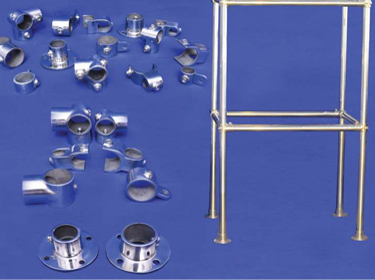
Generally, glass plant and equipment are supported in a rectangular tubular structure. This structure is formed of galvanised mild steel tubing with the cast iron fittings which are described in this catalogue. This type of structure provides enough flexibility for future modifications and is strong enough to support a glass unit.
Following rules should be followed while supporting a glass unit in a tubular structure.
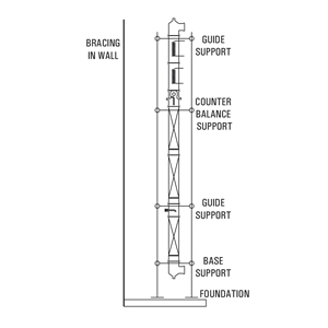
- The structure must be rigid. To give lateral support it must be braced back to the nearest wall or any rigid feature.
- All glass columns are built up from a fixed point on which whole weight of the column should be taken. If total loads exceeds the permissible limits, counter balance supports should be used to relieve excessive weight.
- With change in temperature, glass column and tubular structure expands at different rate. Therefore glass unit must be free for vertical movement above the fixed point. Hence, above the fixed point, guide supports should be used to give lateral support.
For forming the structure,"B" class galvanised tubes, Mild Steel with Epoxy Coated, Stainless Steel 304 & 316 are used in size of 1/2", 1", 1.1/4", 1.1/2" and 2". Cut tubes are available in required length to form a standard size structure. Cut tubes are provided with rubber plug at both the ends.
Tube size
| NB Inches | NB mm | External Diameter |
|---|---|---|
| 1/2" | 15 | 19.5 |
| 1" | 25 | 32.5 |
| 1.1/4" | 30 | 41.5 |
| 1.1/2" | 40 | 48.3 |
| 2" | 50 | 60.3 |
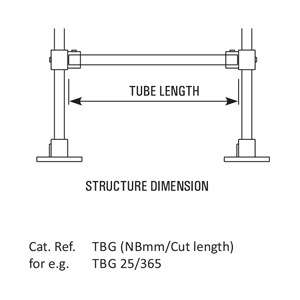
Available cut lengths
| Structure Dimension |
NB (mm) | ||||
|---|---|---|---|---|---|
| 15* | 25* | 30* | 40* | 50* | |
| For Vertical installation | |||||
| 2500 | – | 2500 | – | – | – |
| 3000 | – | 3000 | 3000 | – | – |
| 3500 | – | 3500 | 3500 | – | – |
| 4000 | – | – | 4000 | – | – |
| 6000 | – | 6000 | 6000 | 6000 | 6000 |
| For Frames | |||||
| 400 | – | 365 | 355 | 345 | 335 |
| 500 | – | 465 | 455 | 445 | 435 |
| 600 | – | 565 | 555 | 545 | 535 |
| 800 | – | 765 | 755 | 745 | 735 |
| 1000 | – | 965 | 955 | 1145 | 935 |
| 1200 | – | 1165 | 1155 | 1145 | 1135 |
| 1500 | – | 1465 | 1455 | 1445 | 1435 |
| For Frames | |||||
| 400 | 435 | 445 | 445 | 455 | 465 |
| 500 | 535 | 545 | 545 | 555 | 565 |
| 600 | 635 | 645 | 645 | 655 | 665 |
| 800 | 835 | 845 | 845 | 855 | 865 |
| 1000 | 1035 | 1045 | 1045 | 1055 | 1065 |
| 1200 | 1235 | 1245 | 1245 | 1255 | 1265 |
| 1500 | 1535 | 1545 | 1545 | 1555 | 1565 |
Following structure fittings are available to use with galvanised tubes in order to form a tubular structure for a glass plant. These fittings are made of cast iron. Also available in Stainless Steel 304 & 316 and are suitable to the galvanised tubes described earlier. These slidable fittings are provided with grub screws to fix it at required position on a galvanised tube. These fittings are specially made to construct a tubular structure which provides enough flexibility for future modifications without involving any hammering and welding.
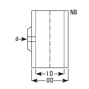
| NB | TUBE DI | ID | OD | d |
|---|---|---|---|---|
| 25 | 32.5 | 35 | 45 | 1/2" |
| 30 | 42.5 | 45 | 55 | 1/2" |
| 40 | 48.3 | 51 | 61 | 1/2" |
| 50 | 60.3 | 63 | 73 | 1/2" |
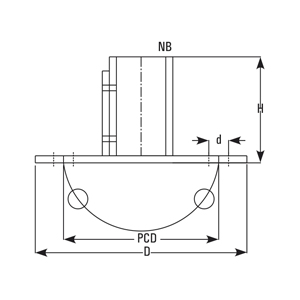
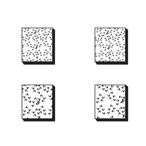
These are to be used with vertical tubes. Holes are provided for foundation.
| Cat. Ref | NB | D | H | PCD | dØ |
|---|---|---|---|---|---|
| BS30* | 30 | 150 | 75 | 110 | 4 x 14Ø |
| BS40 | 40 | 150 | 75 | 110 | 4 x 14Ø |
| BS50 | 50 | 175 | 75 | 125 | 4 x 14Ø |
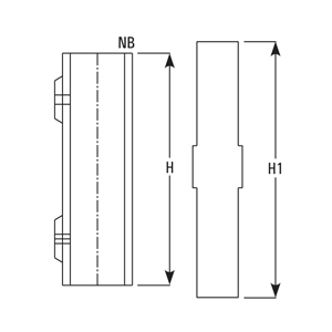
These are generally used to couple the vertical tubes where more length is required.
| Cat. Ref | NB | H | H1 |
|---|---|---|---|
| CL25 | 25 | 150 | 200 |
| CL30 | 30 | 150 | 200 |
| CL40 | 40 | 150 | 200 |
| CL50 | 50 | 150 | 200 |
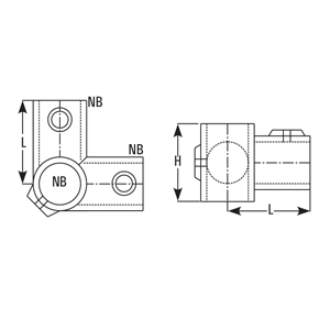
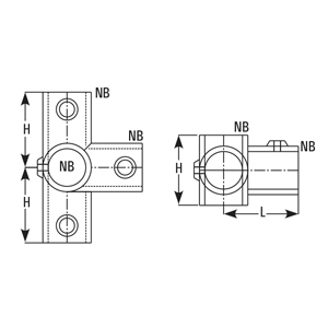
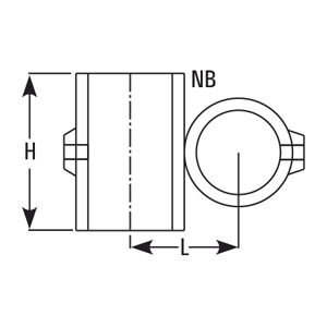
These are used to build frames on vertical tubes.
| Cat. Ref | NB | H | L |
|---|---|---|---|
| BN25* | 25 | 50 | 55 |
| BN30* | 30 | 65 | 70 |
| BN40 | 40 | 70 | 80 |
| BN50 | 50 | 85 | 95 |
| Cat.Ref | NB | H | L |
|---|---|---|---|
| T25* | 25 | 50 | 55 |
| T30* | 30 | 65 | 70 |
| T40 | 40 | 70 | 80 |
| T50 | 50 | 85 | 95 |
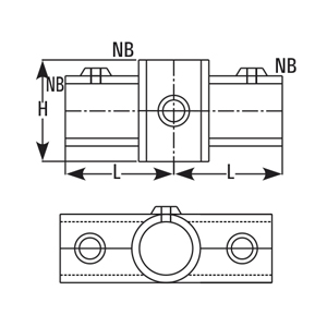
| Cat.Ref | NB | H | L |
|---|---|---|---|
| BN 25 | 25 | 50 | 55 |
| BN30 | 30 | 65 | 70 |
| BN40 | 40 | 70 | 80 |
| BN50 | 50 | 85 | 95 |
| Cat.Ref | NB | H | L |
|---|---|---|---|
| DT25 | 25 | 50 | 55 |
| DT30 | 30 | 65 | 70 |
| DT40 | 40 | 70 | 80 |
| DT50 | 50 | 85 | 95 |
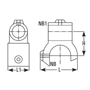
| Cat.Ref | NB | H | L | L1 |
|---|---|---|---|---|
| EBT25* | 25 | 50 | 55 | 50 |
| EBT30* | 30 | 52 | 75 | 60 |
| EBT40 | 40 | 62 | 85 | 60 |
| EBT50 | 50 | 72 | 95 | 60 |
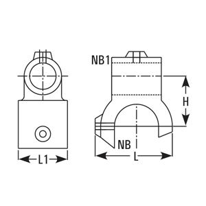
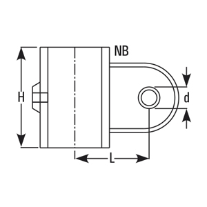
| Cat.Ref | NB | NB1 | H | L | L1 |
|---|---|---|---|---|---|
| UBT25/15* | 25 | 15 | 35 | 65 | 50 |
| UBT30/15* | 30 | 15 | 40 | 75 | 60 |
| UBT40/25 | 40 | 25 | 50 | 85 | 60 |
| UBT50/25 | 50 | 25 | 55 | 95 | 60 |
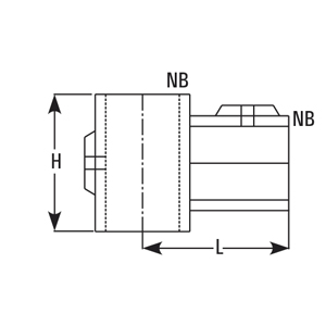
| Cat.Ref | NB | H | L |
|---|---|---|---|
| X25 | 25 | 50 | 45 |
| X30 | 30 | 65 | 55 |
| X40 | 40 | 65 | 70 |
| X50 | 50 | 65 | 85 |
| Cat.Ref | NB | h | L | d |
|---|---|---|---|---|
| SPT15* | 15 | 40 | 35 | 13 |
| SPT25* | 25 | 55 | 50 | 13 |
| SPT30* | 30 | 55 | 57 | 13 |
| SPT40 | 40 | 55 | 62 | 13 |
| SPT50 | 50 | 55 | 67 | 13 |
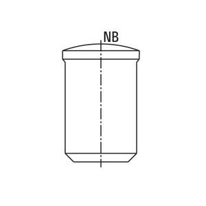
These are used to plug the open ends of galvanised tubes.
| Cat.Ref | NB |
|---|---|
| PLUG15* | 15 |
| PLUG25* | 25 |
| PLUG30* | 30 |
| PLUG40 | 40 |
| PLUG59 | 50 |
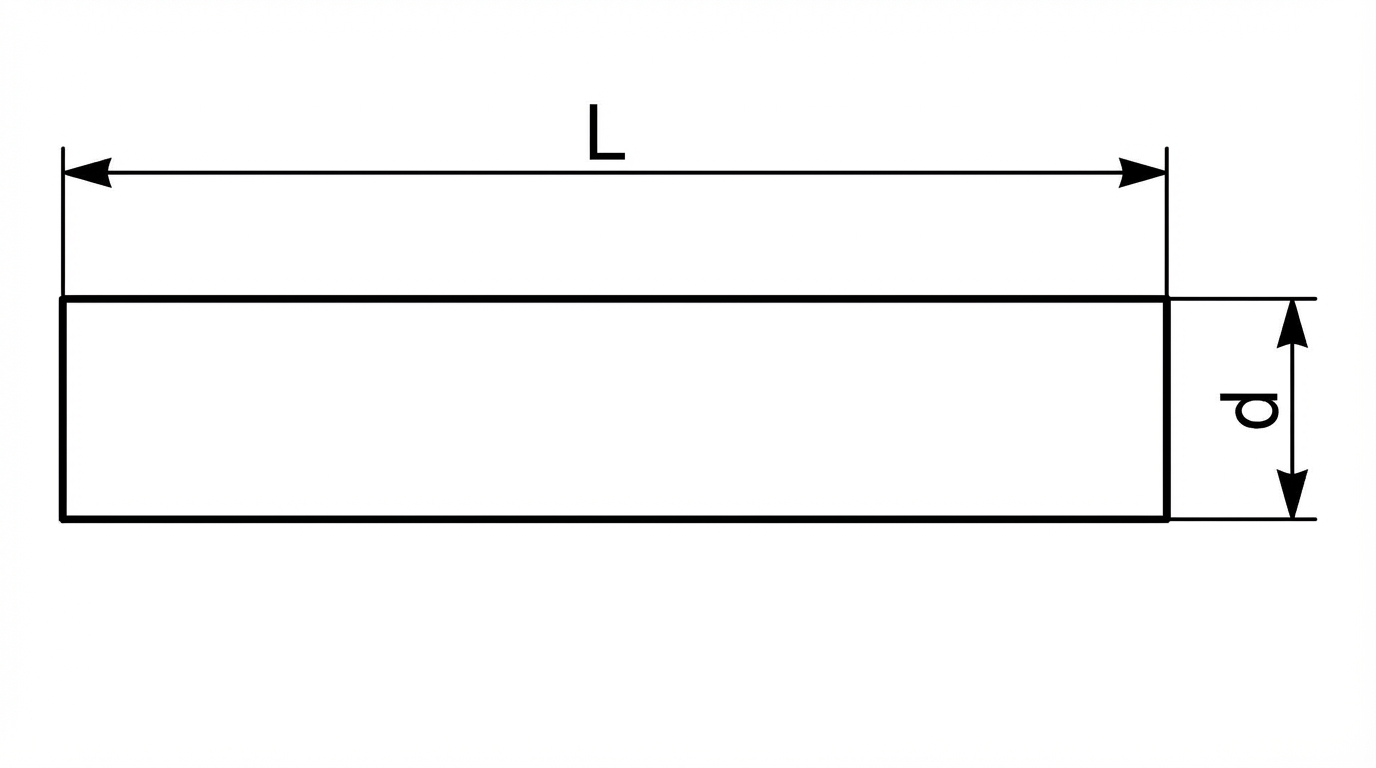
These are used to plug the open ends of galvanised tubes.
| Cat.Ref | d | L |
|---|---|---|
| STUD5/16-150* | 5/16" | 150 |
| STUD3/8-150* | 3/8" | 150 |
| STUD1/2-200 | 1/2" | 200 |
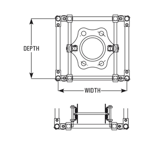
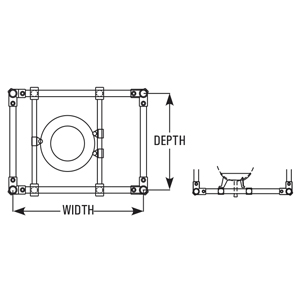
FOR COLUMNS
| DN | Recommended tube size NB (mm) | Minimum Structure size Depth X Width |
|---|---|---|
| 80 | 25 | 500 x 500 |
| S100 | 25 | 500 x 500 |
| 150 | 25, 30 | 600 x 600 |
| 225 | 30 | 800 x 800 |
| 300 | 30 | 800 x 800 |
| 400 | 30 | 1000 x 1000 |
| 450 | 30, 40 | 1000 x 1000 |
| 600 | 40, 50 | 1200 x 1200 |
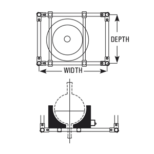
FOR VESSELS (IN HEATING MENTLES)
| Size (Litres) | Recommended tube size NB (mm) | Minimum Structure size Depth X Width |
|---|---|---|
| 20 | 25 | 600 x 600 |
| 50 | 25 | 600 x 800 |
| 100 | 25, 30 | 800 x 800 |
| 200 | 30 | 800 x 1000 |
FOR VESSELS (IN HEATING BATHS)
| Size (Litres) | Recommended tube size NB (mm) | Minimum Structure size Depth X Width |
|---|---|---|
| 20 | 25 | 500 x 600 |
| 50 | 25 | 600 x 800 |
| 100 | 25, 30 | 800 x 1000 |
| 200 | 30 | 800 x 1200 |
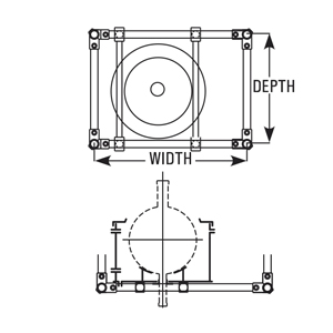
FOR VESSELS (IN VESSEL HOLDERS)
| Size (Litres) | Recommended tube size NB (mm) | Minimum Structure size Depth X Width |
|---|---|---|
| 20 | 25 | 500 x 600 |
| 50 | 25 | 600 x 800 |
| 100 | 25, 30 | 1000 x 1000 |
| 200 | 30 | 1000 x 1000 |
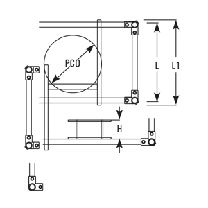
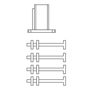
These channel frames are used as fixed support in erection of columns. These are supplied with full threaded jacking rods and U bolts.
| Cat.Ref | PCD | L1 | L | H |
|---|---|---|---|---|
| FCSH225 | 310 | 1000 | 800 | 75 |
| FCSH300 | 3395 | 1000 | 800 | 75 |
| FCSH400 | 495 | 495 | 1000 | 75 |
| FCSH450 | 585 | 1200 | 1000 | 100 |
| FCSH600 | 710 | 1400 | 1200 | 100 |
1. Take one Cast Iron BASE and four foundationBolts,each with 2 nuts.
2. Fit the bolts in BASE so that base is raised up to 50mm from head of bolts.
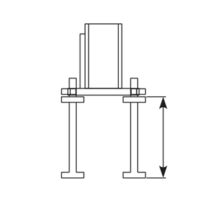
3. Put this assembly on the floor and prepare a rough surface for proper bonding of grouting.
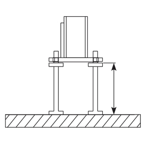
4. Make a concrete block over the bolts of about 200 x 200 mm up to the base of BASE i.e. 150mm high.
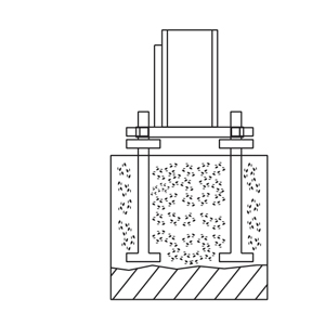
5. Prepare separate block for each BASE instead of making one big common block. For all BASES.
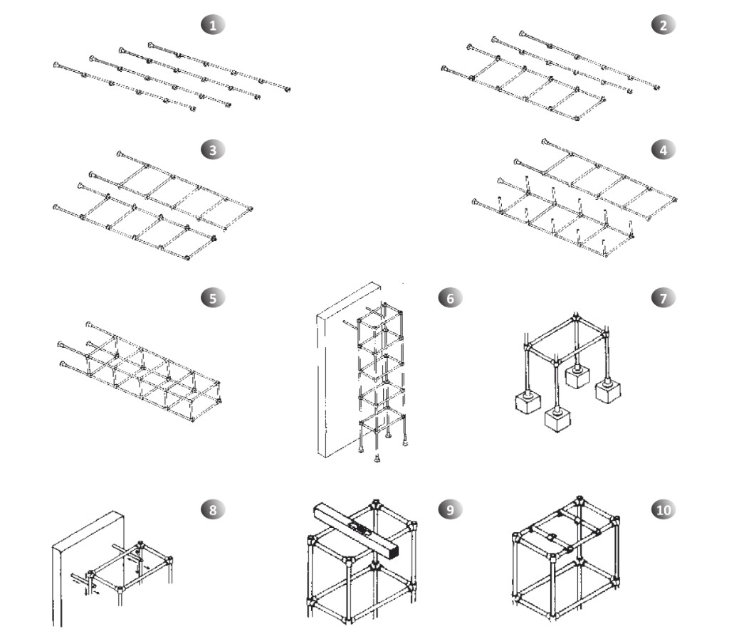
- Mark the position of required fittings on all the Vertical tubes, slide them in correct sequence and lightly Tighten.
- Assemble one side frame of the structure by adding the crosstubes between two vertical tubes.
- Assemble other side frame of the structure by adding the crosstubes between other two vertical tubes.
- Build up the cross tubes in one side frame and Tighten lightly.
- Add the other side frame on it and tighten all the fittings firmly.
- Hoist the structure and brace it to some existing rigid feature.
- Grout the foundation bolts and fix the structure bases with that.
- Adjust bracing to obtain a correct plumb in Structure.
- Adjust the horizontal frames in correct level.
- Assemble the support tubes at their positions.