 Column Components
Column Components
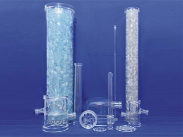
In many operations like reaction, extraction & absorption, the transparency of glass is particular advantage. For such process a range of column components are available in Borosilicate glass which offers many advantages like:
- Inert to almost all chemicals hence no risk of contamination.
- Transparency allows visual monitoring of the process flow patterns, colour changes etc.
- Almost universal resistance to corrosion
- Smooth surface permits easy cleaning & prevents fouling.
Column Components
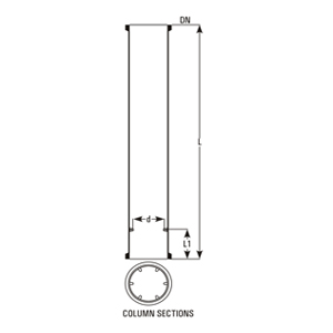
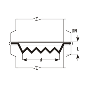
Column can be constructed either by using pipe sections with support plates or using column sections with packing supports. Column sections are provided with fused shelf where packing support can rest.
| Cat. Ref. | DN | L | L1 | Minimum packing Size | Usual packing Size |
|---|---|---|---|---|---|
| CS3/1000 | 80 | 1000 | 75 | 9 | 12 |
| CS4/1000 | 100 | 1000 | 75 | 12 | 15 |
| CS6/1000 | 150 | 1000 | 75 | 15 | 25 |
| CS6/1500 | 150 | 1500 | 75 | 15 | 25 |
| CS9/1000 | 225 | 1000 | 100 | 20 | 25 |
| CS9/1500 | 225 | 1500 | 100 | 20 | 15 |
| CS12/1000 | 300 | 1000 | 100 | 25 | 25 |
| CS12/1500 | 300 | 1500 | 100 | 25 | 25 |
| CS16/1000 | 400 | 1000 | 150 | 25 | 25 |
| CS16/1500 | 400 | 1500 | 150 | 25 | 15 |
| CS18/1000 | 450 | 1000 | 150 | 25 | 25 |
| CS18/1500 | 450 | 1500 | 150 | 25 | 25 |
| CS24/1000 | 600 | 1000 | 200 | 40 | 40 |
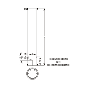
Above column sections can be provided with a thermometer branch below the packing shelf at 20° slope.
| Cat.Ref. | DN | DN1 | L | L1 | d |
|---|---|---|---|---|---|
| CST3/1000 | 80 | 25 | 1000 | 125 | 50 |
| CST4/1000 | 100 | 25 | 1000 | 125 | 75 |
| CST6/1000 | 150 | 25 | 1000 | 125 | 125 |
| CST6/1500 | 150 | 25 | 1500 | 125 | 125 |
| CST9/1000 | 225 | 25 | 1000 | 150 | 175 |
| CST9/1500 | 225 | 25 | 1500 | 150 | 175 |
| CST12/1000 | 300 | 25 | 1000 | 150 | 250 |
| CST12/1500 | 300 | 25 | 1500 | 150 | 250 |
| CST16/1000 | 400 | 25 | 1000 | 200 | 250 |
| CST16/1500 | 400 | 25 | 1500 | 200 | 350 |
| CST18/1000 | 450 | 25 | 1000 | 200 | 400 |
| CST18/1500 | 450 | 25 | 1500 | 200 | 400 |
| CST24/1000 | 600 | 25 | 1000 | 250 | 540 |
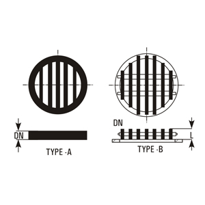
Packing supports Type A are made of fused glass rods. Packing supports Type B (heavy duty) are made of glass plates vertically arranged and tied with PTFE tie rods.
| Cat.Ref. | DN | L | Cross Section Area | Max. Load Kgs. | Minimum Packing | Type |
|---|---|---|---|---|---|---|
| CP3* | 80 | 10 | 45% | 10 | 12 | A |
| CP4* | 100 | 12 | 50% | 15 | 15 | A |
| CP6* | 150 | 15 | 55% | 30 | 25 | A |
| CP9* | 225 | 19 | 60% | 50 | 25 | A |
| CP12* | 300 | 19 | 65% | 75 | 25 | A |
| HD16 | 400 | 70 | 70% | 150 | 25 | B |
| HD18 | 450 | 70 | 70% | 300 | 40 | B |
| HD24 | 600 | 95 | 70% | 300 | 40 | B |
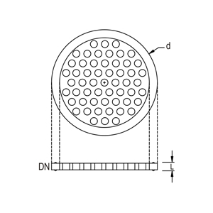
These are used as packing retainers to prevent the packing from lifting due to vapour velocity. These can be clamped between two components without using any gasket.
| Cat.Ref. | DN | d | L |
|---|---|---|---|
| TCP3 | 80 | 99 | 7 |
| TCP4 | 100 | 132 | 9 |
| TCP6 | 150 | 184 | 10 |
| TCP9 | 225 | 254 | 12 |
| TCP12 | 300 | 340 | 16 |
| TCP16 | 400 | 463 | 25 |
| TCP18 | 450 | 525 | 25 |
| TCP24 | 600 | 689 | 30 |
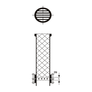
Support Plate Assembly can be coupled with a pipe section (PS), so as to use the pipe section as a column section and to fill packings into it. This system provides following advantages over the conventional system of using column section with a packing support:
Higher cross section area
More packing height.
No separate inventory of column sections.
Delivery period of pipe section are shorter.
This assembly consist of a glass support plate, a metal flange, a PTFE 'O' ring and nut-bolts.
Higher cross section area
More packing height.
No separate inventory of column sections.
Delivery period of pipe section are shorter.
This assembly consist of a glass support plate, a metal flange, a PTFE 'O' ring and nut-bolts.
| Cat.Ref. | DN | L | Cross Section Area | Max. Load Kgs. | Suitable Packing Size |
|---|---|---|---|---|---|
| LBE3* | 80 | 25 | 70% | 20 | 12 |
| LBE4* | 100 | 25 | 70% | 30 | 15 |
| LBE6* | 150 | 50 | 70% | 60 | 25 |
| LBE9* | 225 | 75 | 80% | 90 | 25 |
| LBE12* | 300 | 75 | 80% | 150 | 25 |
Packings required for various pipe sections (Kgs.)
| Pipe Section | Vol(L) | FC | FC 12 | FC 15 | FC 25 | FCB 40 | FCB 50 |
|---|---|---|---|---|---|---|---|
| PS3/1000 | 5 | 3 | 3 | 2 | – | – | – |
| PS4/1000 | 8 | – | 4 | 3 | 3 | – | – |
| PS6/1000 | 18 | – | 9 | 7 | 7 | – | – |
| PS9/1000 | 37 | – | – | 15 | 15 | 15 | – |
| PS12/1000 | 66 | – | – | 17 | 30 | 25 | – |
| PS16/1000 | 125 | – | – | – | 65 | 50 | 53 |
| PS18/1000 | 165 | – | – | – | 90 | 65 | 70 |
| PS24/1000 | 295 | – | – | – | – | 115 | 125 |
Notes of use of Column Packing:
Due to their low bulk densities, Glass Raschig rings are particularly suitable for packing glass columns.
Generally, the ratio of Column diameter to packing diameter should not be less than 8:1.
When using smaller packing size, a small layer of larger packing should be used on packing support, to prevent the smaller packing falling through.
In vacuum application and applications involving high vapour velocities, packing may be lifted and may damage to other parts. To prevent this, a packing retainer (PTFE perforated plates) should be used above the packed section.
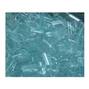
Raschig rings upto 25mm are also available in Neutral glass. 20mm, 30mm, 40mm and 50mm are available in Borosilicate glass 3.3.
| Cat.Ref. | Size | Bulk Density Kg/Ltr | Specific Surface m²/m³ | Glass |
|---|---|---|---|---|
| FC8 | 8x8 | 0.6 | 500 | Neutral |
| FC9 | 9x9 | 0.6 | 500 | Neutral |
| FC12 | 12x12 | 0.5 | 400 | Neutral |
| FC15* | 15x15 | 0.4 | 300 | Neutral |
| FC25* | 25x25 | 0.35 | 250 | Neutral |
| FCB20 | 20x20 | 0.33 | 300 | Borosilicate |
| FCB30 | 30x30 | 0.27 | 180 | Borosilicate |
| FCB40 | 40x40 | 0.22 | 160 | Borosilicate |
| FCB50 | 50x50 | 0.19 | 120 | Borosilicate |
Pall Rings are also available for column packing as per below specification.
| Cat.Ref. | Size | Bulk Density Kg/Ltr | Specific Surface m²/m³ | Glass |
|---|---|---|---|---|
| FCP30 | 30x30 | 0.38 | 234 | Borosilicate |
| FCP40 | 40x40 | 0.32 D | 187 | Borosilicate |
| FCP50 | 50x50 | 0.26 | 140 | Borosilicate |
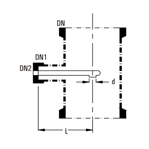
Feed pipe directs the process fluid to the centre of the column.
| Cat.Ref. | DN | DN1 | DN2 | L | d |
|---|---|---|---|---|---|
| FP3 | 80 | 25 | 25 | 100 | 12 |
| FP4 | 100 | 25 | 25 | 125 | 12 |
| FP6 | 150 | 40 | 25 | 150 | 19 |
| FP9 | 225 | 40 | 25 | 175 | 19 |
| FP12 | 300 | 40 | 25 | 225 | 19 |
| FP16 | 400 | 40 | 25 | 275 | 19 |
| FP18 | 450 | 40 | 25 | 300 | 19 |
| FP24 | 600 | 50 | 40 | 450 | 25 |
DN refers to the nominal diameter of the column.
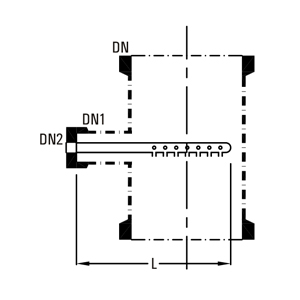
In column feed spargers, holes are provided at three sides of pipe.
| Cat.Ref. | DN | DN1 | DN2 | L | Holes |
|---|---|---|---|---|---|
| SPG3 | 80 | 25 | 25 | 125 | 21x2mm |
| SPG4 | 100 | 25 | 25 | 150 | 21x2mm |
| SPG6 | 150 | 40 | 25 | 200 | 27x2mm |
| SPG9 | 225 | 40 | 25 | 275 | 27x2mm |
| SPG12 | 300 | 40 | 25 | 350 | 30x3mm |
| SPG16 | 400 | 40 | 25 | 450 | 39x3mm |
| SPG18 | 450 | 40 | 25 | 500 | 39x3mm |
| SPG24 | 600 | 50 | 40 | 650 | 60x3mm |
DN refers to the nominal diameter of the column.
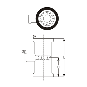
Spray feed section are provided with circular tube having holes at the bottom.
| Cat.Ref. | DN | DN1 | L | L1 | Holes |
|---|---|---|---|---|---|
| FR3 | 80 | 25 | 200 | 100 | 21x2mm |
| FR4 | 100 | 25 | 250 | 125 | 21x2mm |
| FR6 | 150 | 40 | 250 | 125 | 27x2mm |
| FR9 | 225 | 40 | 250 | 125 | 27x2mm |
| FR12 | 300 | 40 | 300 | 150 | 30x3mm |
For bigger columns, Spray feed pipe with Unequal Tee should be used.
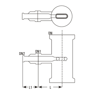
Spray feed pipes are provided with oval tube having holes at the bottom. These should be used with unequal tees.
| Cat.Ref. | DN | DN1 | DN2 | L | L1 | Holes Size | Tee Suitable |
|---|---|---|---|---|---|---|---|
| FD6 | 150 | 80 | 25 | 225 | 125 | 27x2mm | PTU6/3 |
| FD9 | 225 | 100 | 25 | 25 | 150 | 27x2mm | PTU9/4 |
| FD12 | 300 | 150 | 25 | 400 | 200 | 30x3mm | PTU12/6 |
| FD16 | 400 | 150 | 50 | 500 | 200 | 39x3mm | PTU16/6 |
| FD18 | 450 | 150 | 50 | 550 | 200 | 39x3mm | PTU18/6 |
| FD24 | 600 | 150 | 50 | 700 | 200 | 60x3mm | PTU24/6 |
DN refers the nominal diameter of the column.
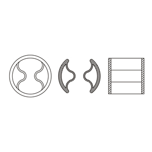
PTFE redistributors are used to prevent channeling in columns. These can be clamped between two components without using any gasket.
| Cat.Ref. | DN | d | L |
|---|---|---|---|
| TL3 | 80 | 55 | 20 |
| TL4 | 100 | 80 | 20 |
| TL6 | 150 | 100 | 20 |
| TL9 | 225 | 175 | 22 |
| TL12 | 300 | 215 | 25 |
| TL16 | 400 | 315 | 25 |
| TL18 | 450 | 365 | 30 |
| L24 | 600 | 420 | 30 |
| Cat. Ref. | DN | DN1 | DN2 | L | L1 | L2 |
|---|---|---|---|---|---|---|
| CA3/1/1 | 80 | 25 | 25 | 150 | 75 | 100 |
| CA3/1.5/1 | 80 | 40 | 25 | 175 | 100 | 100 |
| CA3/2/1 | 80 | 50 | 25 | 175 | 100 | 100 |
| CA4/1/1 | 100 | 25 | 25 | 150 | 75 | 125 |
| CA4/1.5/1 | 100 | 40 | 25 | 175 | 100 | 125 |
| CA4/2/1 | 100 | 50 | 25 | 225 | 125 | 125 |
| CA4/3/1 | 100 | 80 | 25 | 225 | 125 | 125 |
| CA6/1/1 | 150 | 25 | 25 | 200 | 100 | 150 |
| CA6/1.5/1 | 150 | 40 | 25 | 200 | 100 | 150 |
| CA6/2/1 | 150 | 50 | 25 | 250 | 125 | 150 |
| CA6/3/1 | 150 | 80 | 25 | 250 | 150 | 150 |
| CA6/4/1 | 150 | 100 | 25 | 275 | 150 | 175 |
| CA9/1.5/1.5 | 225 | 40 | 40 | 250 | 150 | 175 |
| CA9/2/1.5 | 225 | 50 | 40 | 250 | 150 | 175 |
| CA9/3/1.5 | 225 | 80 | 40 | 300 | 175 | 200 |
| CA9/4/1.5 | 225 | 100 | 40 | 350 | 175 | 200 |
| CA9/6/1.5 | 225 | 150 | 40 | 400 | 200 | 250 |
| CA12/1.5/1.5 | 300 | 40 | 40 | 300 | 150 | 225 |
| CA12/2/1.5 | 300 | 50 | 40 | 300 | 150 | 225 |
| CA12/3/1.5 | 300 | 80 | 40 | 300 | 150 | 250 |
| CA12/4/1.5 | 300 | 100 | 40 | 350 | 175 | 250 |
| CA12/6/1.5 | 300 | 150 | 40 | 425 | 225 | 250 |
| CA12/9/1.5 | 300 | 225 | 40 | 450 | 225 | 300 |
| CA16/2/2 | 400 | 50 | 50 | 400 | 200 | 300 |
| CA16/3/2 | 400 | 80 | 50 | 450 | 250 | 300 |
| CA16/4/2 | 400 | 100 | 50 | 450 | 250 | 300 |
| CA16/6/2 | 400 | 150 | 50 | 550 | 300 | 350 |
| CA16/9/2 | 400 | 225 | 50 | 550 | 300 | 350 |
| CA18/2/2 | 450 | 50 | 50 | 400 | 200 | 325 |
| CA18/3/2 | 450 | 80 | 50 | 450 | 250 | 350 |
| CA18/4/2 | 450 | 100 | 50 | 450 | 250 | 350 |
| CA18/6/2 | 450 | 150 | 50 | 550 | 300 | 350 |
| CA18/9/2 | 450 | 225 | 50 | 550 | 300 | 400 |
| CA18/12/2 | 450 | 300 | 50 | 750 | 400 | 400 |
| CA24/2/2 | 600 | 50 | 50 | 450 | 200 | 400 |
| CA24/3/2 | 600 | 80 | 50 | 500 | 250 | 400 |
| CA24/4/2 | 600 | 100 | 50 | 500 | 250 | 400 |
| CA24/6/2 | 600 | 150 | 50 | 650 | 300 | 450 |
| CA24/9/2 | 600 | 225 | 50 | 650 | 300 | 450 |
| CA24/12/2 | 600 | 300 | 50 | 800 | 400 | 500 |
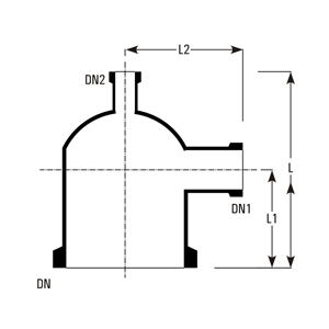
Column adaptors with DN2 of different size (maximum equaling to DN1) can be manufactured with the same dimensions.
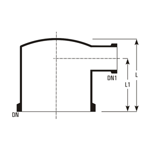
These are generally used as headers of shell and tube heat exchangers and columns.
| Cat.Ref. | DN | DN1 | L | L1 |
|---|---|---|---|---|
| CA3/1 | 80 | 25 | 100 | 75 |
| CA3/1.5 | 80 | 40 | 125 | 100 |
| CA4/1 | 100 | 25 | 100 | 75 |
| CA4/1.5 | 100 | 40 | 125 | 100 |
| CA6/1 | 150 | 25 | 150 | 100 |
| CA6/1.5 | 150 | 40 | 150 | 100 |
| CA6/2 | 150 | 50 | 200 | 125 |
| CA6/3 | 150 | 80 | 200 | 150 |
| CA9/1.5 | 225 | 40 | 200 | 150 |
| CA9/2 | 225 | 50 | 200 | 150 |
| CA9/3 | 225 | 80 | 250 | 175 |
| CA9/4 | 225 | 100 | 250 | 175 |
| CA12/2 | 300 | 50 | 250 | 150 |
| CA12/3 | 300 | 80 | 250 | 150 |
| CA12/4 | 300 | 100 | 300 | 175 |
| CA12/6 | 300 | 150 | 350 | 225 |
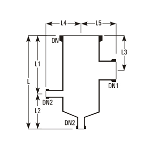
| Cat.Ref. | DN | DN1 | DN2 | L | L1 | L2 | L3 | L4 | L5 |
|---|---|---|---|---|---|---|---|---|---|
| CAM4/2/1/1 | 100 | 50 | 25 | 450 | 300 | 150 | 200 | 125 | 125 |
| CAM6/3/1/1 | 150 | 80 | 25 | 450 | 300 | 150 | 200 | 150 | 150 |
| CAM9/3/1/1 | 225 | 80 | 25 | 450 | 300 | 150 | 200 | 175 | 200 |
| CAM12/3/1/1 | 300 | 80 | 25 | 450 | 300 | 150 | 200 | 225 | 250 |
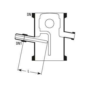
Manually Operated
Reflux dividers are used to take off the distillate from the column. Usually a valve is to be fitted on distillate outlet which controls the reflux coarsely.
Reflux dividers are used to take off the distillate from the column. Usually a valve is to be fitted on distillate outlet which controls the reflux coarsely.
| Cat.Ref. | DN | DN1 | DN2 | L | L1 | Free Cross Section Cm² | Max. Product L/hr |
|---|---|---|---|---|---|---|---|
| RDA3* | 80 | 25 | 25 | 200 | 100 | 20 | 300 |
| RDA4* | 100 | 25 | 25 | 250 | 150 | 50 | 500 |
| RDA6* | 150 | 25 | 25 | 250 | 150 | 100 | 700 |
| RDA9* | 225 | 25 | 25 | 375 | 150 | 150 | 900 |
| RDA12* | 300 | 25 | 25 | 375 | 150 | 250 | 1100 |
| RDA16 | 400 | 40 | 40 | 500 | 200 | 350 | 1300 |
| RDA18 | 450 | 40 | 40 | 600 | 275 | 500 | 1500 |
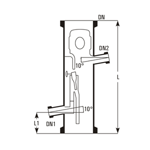
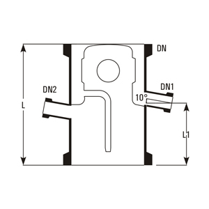
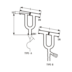
Magnetically Operated
These reflux dividers are to be used with an electro-magnet and a timer. These have a swinging funnel mechanism which is operated magnetically from outside to remove the condensate or to return the reflux. Through this, correct control of reflux-ratio is possible. Funnel remains at 100% reflux position while magnet is inactive.
These reflux dividers are to be used with an electro-magnet and a timer. These have a swinging funnel mechanism which is operated magnetically from outside to remove the condensate or to return the reflux. Through this, correct control of reflux-ratio is possible. Funnel remains at 100% reflux position while magnet is inactive.
| Cat.Ref. | DN | DN1 | DN2 | L | L1 | Free Cross Section Cm² | Max. Product L/hr |
|---|---|---|---|---|---|---|---|
| RHM3 | 80 | 25 | 25 | 375 | 75 | 20 | 90 |
| RHM4 | 100 | 25 | 25 | 400 | 75 | 50 | 180 |
| RHM6 | 150 | 25 | 25 | 450 | 100 | 100 | 300 |
| RHM9 | 225 | 25 | 25 | 550 | 100 | 150 | 500 |
| RHM12 | 300 | 25 | 25 | 700 | 100 | 250 | 650 |
| RHM16 | 400 | 40 | 40 | 800 | 150 | 350 | 1000 |
| RHM18 | 450 | 40 | 40 | 900 | 150 | 500 | 1300 |
DN2 is used for insertion of a Thermometer Pocket. A bellow is recommended on the distillate outlet DN1 for manually operated dividers. A liquid seal is recommended on the distillate outlet of the magnetically operated reflux divider to prevent the vapour passing directly to the receiver.
| Cat.Ref. | DN | DN1 | DN2 | L |
|---|---|---|---|---|
| RPH3 | 80 | 25 | 25 | 250 |
| RPH4 | 100 | 25 | 25 | 250 |
| RPH6 | 150 | 40 | 25 | 250 |
| RPH9 | 225 | 40 | 50 | 375 |
| RPH12 | 300 | 40 | 50 | 375 |
These thermometer pockets are to be used with reflux dividers or column sections. DN refers to the nominal diameter of the Reflux divider or Column.
| Cat.Ref. | DN | DN1 | d | L |
|---|---|---|---|---|
| TP3* | 80 | 25 | 12 | 75 |
| TP4* | 100 | 25 | 12 | 100 |
| TP6* | 150 | 25 | 12 | 125 |
| TP9* | 225 | 25 | 12 | 150 |
| TP12* | 300 | 25 | 12 | 200 |
| TP16 | 400 | 40 | 19 | 250 |
| TP18 | 450 | 40 | 19 | 300 |
Liquid seals are to be fitted on the distillate outlet of magnetically operated reflux divider. This prevents the passing of vapour directly to the receiver.
| Cat.Ref. | DN | DN1 | L | Type |
|---|---|---|---|---|
| LS1* | 25 | 25 | 200 | A |
| LS1.5 | 40 | 25 | 300 | A |
| LSV1 | 25 | – | 200 | B |
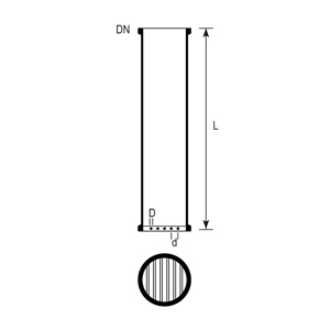
PACKING SUPPORT
Surya introduce single piece column section with inbuilt packing support.
Advantages of this column against conventional column section:
• Ease in installation being a single piece instead of two pieces
• There is no need to maintain stock of CS and packing support
• Increases effective packed height which results in to increase in efficiency.
• Zero maintenance against column flooding.
| Cat.Ref. | DN | D | d | L | Max Load Kgs | Suitable Packing Size |
|---|---|---|---|---|---|---|
| CSP3/1000 | 80 | 10 | 10 | 1000 | 20 | 12 |
| CSP4/1000* | 100 | 10 | 14 | 1000 | 30 | 15 |
| CS6P/1000* | 150 | 12 | 22 | 1000 | 60 | 25 |
| CSP9P/1000* | 225 | 12 | 22 | 1000 | 90 | 25 |
| CSP12/1000* | 300 | 12 | 22 | 1000 | 150 | 25 |
These are generally used as headers of shell and tube heat exchangers and columns.
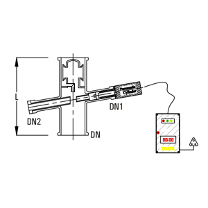
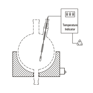
This instrument is mainly used to monitor the temperature of liquid in a glass vessel in a typical Glass Distillation Unit.
The instrument consists of a Temperature indicator and a Resistance Temperature Detectors (RTD). The instrument works on 230V, 50Hz power supply. This displays the temperature in degree Centigrades in three and half digits of 12.5mm character height.
| Cat.Ref. | Vessel size | RTD Length |
|---|---|---|
| DTI20 | 20 | 400 |
| DTI50 | 50 | 500 |
| DTI100 | 100 | 600 |
| DTI200 | 200 | 700 |
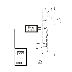
Electro-magnets are used to operate Magnetically operated Reflux dividers. When 'On' the magnet attracts the swinging funnel of the reflux divider so that distillate can be taken off.
Electro-magnets are to be mounted outside the glass column, just near to the reflux divider, with the help of adjustable fittings. These are designed to use with Timers to maintain correct ratio between 'Off' and 'On' timings of its activation.
Electro-magnets work on 220V DC power supply, for which an output socket is provided in the Timers.
| Cat.Ref. | Type |
|---|---|
| RPM | Non-flameproof |
| RPF | Flameproof |
Timers are designed to use with Electro-magnets to provide a correct ratio of reflux and distillate when operating a Magnetically operated reflux divider.
Timers work on a power supply of 230V, 50Hz.
Timers work on a power supply of 230V, 50Hz.
| Cat.Ref. | Type |
|---|---|
| QRT | Flameproof |