 Coupling and Gaskets
Coupling and Gaskets
In this section we have covered coupling to join glass components together as well as to join glass components
The couplings used with glass equipment are important from two main points of view :
1.They must ensure the effective seal of the joint.
2.They should not induce any undue stress in the glass.
3.They must be reliable in all service conditions.
In this section we have covered couplings to join glass components together as well as to join glass component with a other metal equipment.
PTFE bellows are available for normal and vacuum applications together with flanges to connect them to glass or non-glass equipment.
Coupling and Gaskets
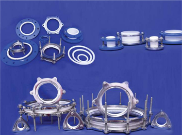
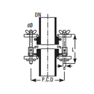
A complete coupling is a set of two backing flanges with insert and nut-bolts. Complete set of flanges required to make a joint & standard ones are available in Cast Iron. Also available in other MOC like Stainless Steel 304 & 316, Siliumin.
| Cat.Ref. | DN | Flanges Cat.Ref. | Flanges Qty | Inserts Cat.Ref. | Inserts Qty | d | L | Nuts-Bolts Qty |
|---|---|---|---|---|---|---|---|---|
| CT0.5 | 12 | CF0.5 | 2nos | CN0.5 | 2nos | 1/4" | 50 | 3nos |
| CT0.7 | 15 | CF0.7 | 2nos | CN0.7 | 2nos | 1/4" | 50 | 3nos |
| CT1* | 25 | CF1 | 2nos | CN1 | 2nos | 5/16" | 65 | 3nos |
| CT1.5* | 40 | CF1.5 | 2nos | CN1.5 | 2nos | 5/16" | 65 | 3nos |
| CT2* | 50 | CF2 | 2nos | CN2 | 2nos | 5/16" | 75 | 3nos |
| CT3* | 80 | CF3 | 2nos | CN3 | 2nos | 5/16" | 75 | 6nos |
| CT4* | 100 | CF4 | 2nos | CN4 | 2nos | 5/16" | 100 | 6nos |
| CT6* | 150 | CF6 | 2nos | CN6 | 2nos | 5/16" | 100 | 6nos |
| CT9* | 225 | CF9 | 2nos | CN9 | 2nos | 3/8" | 125 | 8nos |
| CT12* | 300 | CF12 | 2nos | CN12 | 2nos | 3/8" | 150 | 12nos |
| CT16 | 400 | CF16 | 2nos | CN16 | 2nos | 3/8" | 150 | 12nos |
| CT18* | 450 | CF18 | 2nos | CN18 | 2nos | 1/2" | 150 | 12nos |
| CT24 | 600 | CF24 | 2nos | CN24 | 2nos | 1/2" | 150 | 12nos |
| CT32 | 800 | CF32 | 2nos | CN32 | 2nos | 1/2" | 150 | 24nos |
For easy & fast opening or closing of couplings as quick as possible without using tools, the Quick Release Coupling is an ideal solution. In case of solid charging material to reaction or addition vessels, we recommend to use our Quick Release Coupling.
Quick Release coupling are offered in cast iron & stainless steel material as per the requirement. Quick Release Coupling is available from DN 80 to DN 300 sizes.
| Cat.Ref. | DN | PCD | nxdØ |
|---|---|---|---|
| QCT3 | 80 | 133 | 6x9Ø |
| QCT4 | 100 | 178 | 6x9Ø |
| QCT6 | 150 | 254 | 6x9Ø |
| QCT9 | 225 | 310 | 8x11Ø |
| QCT12 | 300 | 395 | 12x11Ø |
Backing flanges are used to couple a glass end to a glass end or to a bellow. Backing flanges are made of cast iron and are used with Inserts.
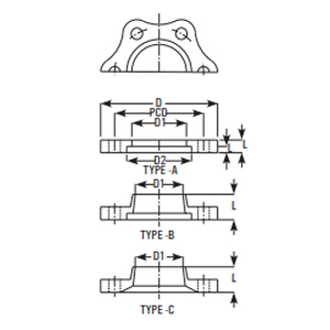
| Cat.Ref. | DN | D | D1 | D2 | PCD | n x dØ | L | L1 | Type |
|---|---|---|---|---|---|---|---|---|---|
| CF0.5 | 12 | 50 | 25 | 28 | 38 | 3 x 7Ø | 6 | 3 | A |
| CF0.7 | 15 | 65 | 29 | 37 | 48 | 3 x 7Ø | 6 | 3.5 | A |
| CF1 | 25 | 92 | 43 | 51 | 70 | 3 x 9Ø | 10 | 6 | A |
| CF1.5 | 40 | 110 | 58 | 66 | 86 | 3 x 9Ø | 10 | 6 | A |
| CF2 | 50 | 120 | 70 | 81 | 98 | 3 x 9Ø | 12 | 8 | A |
| CF3 | 80 | 155 | 101 | 112 | 133 | 6 x 9Ø | 12 | 8 | A |
| CF4 | 100 | 200 | 134 | 148 | 178 | 6 x 9Ø | 12 | 8 | A |
| CF6 | 150 | 275 | 186 | 196 | 254 | 6 x 9Ø | 15 | 8 | A |
| CF9 | 225 | 350 | 260 | 282 | 310 | 8 x 11Ø | 28 | 8 | B |
| CF12 | 300 | 425 | 342 | 363 | 395 | 12 x 11Ø | 34 | 8 | B |
| CF16 | 400 | 525 | 467 | 476 | 495 | 12 x 12Ø | 22 | 8 | A |
| CF18 | 450 | 630 | 537 | 557 | 585 | 12 x 14Ø | 37 | 8 | B |
| CF24 | 600 | 755 | 643 | 690 | 710 | 12 x 14Ø | 50 | 5 | C |
| CF32 | 800 | 990 | 861 | 922 | 950 | 24 x 14Ø | 67 | 5 | C |
Split ring type inserts are used with backing flanges. These are made of Cast iron with a non-asbestos lining. In addition, inserts made of suitable composite rubber material are available for 25 DN to 150 DN size. New Non-Asbestos (make Champion, Klinger) inserts are being introduced for 25 DN to 300 DN.
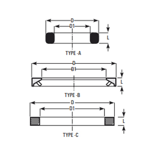
| Cat.Ref. | DN | D | D1 | L | Type |
|---|---|---|---|---|---|
| CN0.5 | 12 | 28 | 20 | 8 | A |
| CN0.7 | 15 | 37 | 22 | 8 | A |
| CN1 | 25 | 50 | 34 | 10 | A |
| CN1.5 | 40 | 65 | 48 | 10 | A |
| CN2 | 50 | 80 | 61 | 8 | B |
| CN3 | 80 | 111 | 90 | 9 | B |
| CN4 | 100 | 147 | 119 | 10 | B |
| CN6 | 150 | 195 | 168 | 10 | B |
| CN9 | 225 | 280 | 240 | 10 | B |
| CN12 | 300 | 361 | 324 | 10 | B |
| CN16 | 400 | 474 | 431 | 12 | B |
| CN18 | 450 | 555 | 500 | 18 | B |
| CN24 | 600 | 684 | 634 | 10 | C |
Adaptor backing flanges are used to couple a glass end to the flange having different bolt configuration. These flanges are made of cast iron and are supplied with inserts.
These are particularly used to fit a glass equipment on a non-glass equipment like Glass-lined Reactor etc.
Adaptor backing flanges are generally supplied undrilled. However, if specified, these can be supplied drilled as per "Table E", "Table F" and "ASA150" standards.
Drilled to Table E
| Cat.Ref. | PCD | n x dØ |
|---|---|---|
| CFA0.5/E | 62 | 4 x 7Ø |
| CFA0.7/E | 62 | 4 x 7Ø |
| CFA1/E | 82 | 4 x 12Ø |
| CFA1.5/E | 98 | 4 x 12Ø |
| CFA2/E | 114 | 4 x 16Ø |
| CFA3/E | 146 | 4 x 16Ø |
| CFA4/E | 178 | 8 x 16Ø |
| CFA6/E | 235 | 8 x 19Ø |
| CFA9/E | 324 | 12 x 19Ø |
| CFA12/E | 406 | 12 x 23Ø |
Drilled to ASA 150
| Cat.Ref. | PCD | n x dØ |
|---|---|---|
| CFA0.5/A | 62 | 4 x 7Ø |
| CFA0.7/A | 62 | 4 x 7Ø |
| CFA1/A | 79 | 4 x 12Ø |
| CFA1.5/A | 98 | 4 x 12Ø |
| CFA2/A | 121 | 4 x 16Ø |
| CFA3/A | 152 | 4 x 16Ø |
| CFA4/A | 190 | 8 x 16Ø |
| CFA6/A | 241 | 8 x 19Ø |
| CFA9/A | 298 | 8 x 19Ø |
| CFA12/A | 432 | 12 x 23Ø |
Undrilling flanges
| Cat.Ref. | DN | D | D1 | D2 | L |
|---|---|---|---|---|---|
| CFA0.5 | 12 | 80 | 25 | 28 | 6 |
| CFA0.7 | 15 | 85 | 29 | 37 | 6 |
| CFA1 | 25 | 115 | 43 | 51 | 10 |
| CFA1.5 | 40 | 150 | 58 | 66 | 10 |
| CFA2 | 50 | 165 | 70 | 81 | 12 |
| CFA3 | 80 | 200 | 101 | 112 | 12 |
| CFA4 | 100 | 220 | 134 | 148 | 12 |
| CFA6 | 150 | 285 | 186 | 196 | 15 |
| CFA9 | 225 | 395 | 260 | 282 | 15 |
| CFA12 | 300 | 445 | 342 | 363 | 18 |
Drilled to Table F
| Cat.Ref. | PCD | n x dØ |
|---|---|---|
| CFA0.5/F | 67 | 4 x 7Ø |
| CFA0.7/F | 67 | 4 x 7Ø |
| CFA1/F | 87 | 4 x 16Ø |
| CFA1.5/F | 105 | 4 x 16Ø |
| CFA2/F | 127 | 4 x 16Ø |
| CFA3/F | 165 | 8 x 16Ø |
| CFA4/F | 190 | 8 x 16Ø |
| CFA6/F | 260 | 12 x 19Ø |
| CFA9/F | 356 | 12 x 23Ø |
| CFA12/F | 438 | 16 x 23Ø |
These PTFE O rings are specially made to use as gaskets in glass fittings. These are provided with a collar which helps to locate it on the glass end correctly.
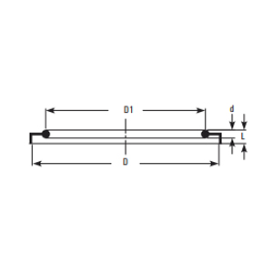
| Cat.Ref. | DN | D | D1 | d | L |
|---|---|---|---|---|---|
| TR0.5 | 12 | 26 | 18 | 3 | 5 |
| TR0.7 | 15 | 28 | 17 | 3 | 5 |
| TR1* | 25 | 42 | 33 | 3 | 5 |
| TR1.5* | 40 | 57 | 48 | 3 | 5 |
| TR2* | 50 | 70 | 59 | 3 | 5 |
| TR3* | 80 | 100 | 88 | 3 | 5 |
| TR4* | 100 | 134 | 119 | 4 | 6 |
| TR6* | 150 | 186 | 168 | 4 | 6 |
| TR9* | 225 | 260 | 236 | 4 | 7 |
| TR12* | 300 | 342 | 318 | 4 | 7 |
| TR16 | 400 | 467 | 435 | 6 | 7 |
| TR18* | 450 | 527 | 490 | 6 | 7 |
| TR24 | 600 | 686 | 640 | 8 | 10 |
| TR32 | 800 | 910 | 885 | 10 | 12 |
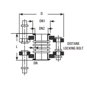
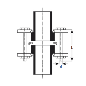
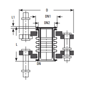
These bellows are used in installation of glass equipment for safe branching of pipelines, to accommodate odd degrees and variation in length. Bellows are supplied along with required bellow flanges and nut-bolts. Distance-locking bolts are provided to avoid excessive compression or contraction of the bellow.
These bellows are used in installation of glass equipment for following purposes :
- To provide safe branching of pipelines from the main glass equipment.
- To accommodate odd degrees and variation in length.
Bellows are supplied along with required bellow flanges and nut-bolts.
Distance - locking bolts are provided to avoid excessive compression or contraction of the bellow. Gaskets are not required where bellows are used. For drilling details, refer "Bellow flanges".
Line bellows
These can withstand a temperature of 200 °C under normal atmospheric conditions.
| Cat.Ref. | DN | D | D1 | D2 | L |
|---|---|---|---|---|---|
| FBN0.5 | 12 | 50 | 24 | 16 | 50 |
| FBN0.7 | 15 | 64 | 28 | 17 | 55 |
| FBN1* | 25 | 95 | 41 | 31 | 65 |
| FBN1.5* | 40 | 105 | 56 | 43 | 65 |
| FBN2* | 50 | 120 | 69 | 55 | 65 |
| FBN3* | 80 | 155 | 98 | 82 | 65 |
| FBN4* | 100 | 200 | 132 | 111 | 65 |
| FBN6* | 150 | 275 | 184 | 162 | 65 |
| FBN9* | 225 | 350 | 258 | 230 | 65 |
| FBN12 | 300 | 420 | 340 | 308 | 65 |
Vacuum bellows
For pipelines of 80 DN and above operating under vacuum, the bellows are provided with an internal sleeve which supports the convolutions without affecting the flexibility of the bellow. These bellows can withstand a temperature of 200 °C under full vacuum. For size up to 50 DN, line bellows can be used for these applications.
| Cat.Ref. | DN | D | D1 | D2 | L | L1 | t |
|---|---|---|---|---|---|---|---|
| VB3 | 80 | 155 | 98 | 82 | 70 | 5 | 3.0 |
| VB4 | 100 | 200 | 132 | 111 | 70 | 5 | 3.5 |
| VB6 | 150 | 275 | 184 | 162 | 70 | 5 | 4.0 |
| VB9 | 225 | 350 | 253 | 230 | 70 | 5 | 5.0 |
| VB12 | 300 | 420 | 338 | 308 | 70 | 5 | 5.0 |
These bellows are used in installation of glass equipment for following purposes :
- To minimize the transfer of vibrations from the rotating equipments which are connected to the glass assembly.
- To accommodate the thermal expansion of any metallic (non-glass) equipment which are connected to the glass pipeline.
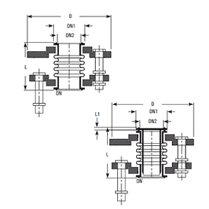
These are similar to the bellows for glass-to-glass in construction, but having adaptor bellow flange at one end. Generally this adaptor flange is supplied undrilled so that it can be drilled as per the configuration of mating flange. However, this adaptor bellow flange can be supplied drilled as per "Table E", "Table F" or "ASA 150" standards, if specified.
Line bellows
| Cat.Ref. Undrilled | Cat.Ref. Table E | Cat.Ref. Table F | Cat.Ref. ASA 150 | DN | D | L |
|---|---|---|---|---|---|---|
| FBF0.5 | FBF0.5/E | FBF0.5/F | FBF0.5/A | 12 | 80 | 80 |
| FBF0.7 | FBF0.7/E | FBF0.7/F | FBF0.7/A | 15 | 85 | 55 |
| FBF1* | FBF1/E | FBF1/F | FBF1/A | 25 | 115 | 60 |
| FBF1.5* | FBF1.5/E | FBF1.5/F | FBF1.5/A | 40 | 150 | 65 |
| FBF2* | FBF2/E | FBF2/F | FBF2/A | 50 | 165 | 65 |
| FBF3* | FBF3/E | FBF3/F | FBF3/A | 80 | 200 | 65 |
| FBF4* | FBF4/E | FBF4/F | FBF4/A | 100 | 220 | 65 |
| FBF6* | FBF6/E | FBF6/F | FBF6/A | 150 | 285 | 65 |
| FBF9* | FBF9/E | FBF9/F | FBF9/A | 225 | 395 | 65 |
| FBF12 | FBF12/E | FBF12/F | FBF12/A | 300 | 445 | 65 |
Vacuum bellows
| Cat.Ref. Undrilled | Cat.Ref. Table E | Cat.Ref. Table F | Cat.Ref. ASA 150 | DN | D | L |
|---|---|---|---|---|---|---|
| VBF3 | VBF3/E | VBF3/F | VBF3/A | 80 | 200 | 70 |
| VBF4 | VBF4/E | VBF4/F | VBF4/A | 100 | 220 | 70 |
| VBF6 | VBF6/E | VBF6/F | VBF6/A | 150 | 285 | 70 |
| VBF9 | VBF9/E | VBF9/F | VBF9/A | 225 | 395 | 70 |
| VBF12 | VBF12/E | VBF12/F | VBF12/A | 300 | 445 | 70 |
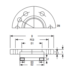
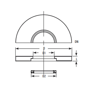
Bellow flanges are used to fit a bellow to a glass component. Standard Bellow are made Cast Iron. Cast Iron with Epoxy Coated, Cast Iron with PTFE coated, Aluminum, Silumin, Stainless Steel, 304 & 316 and are used in FBV, VB, FB type bellows. These are provided with two holes at 180° for Distance-locking bolts and are supplied with a split ring.
| Cat.Ref. Undrilled | DN | D | D1 | D2 | D3 | L | L1 | L2 |
|---|---|---|---|---|---|---|---|---|
| BF0.5 | 12 | 50 | 25 | 28 | 20 | 6 | 3 | 6 |
| BF0.7 | 15 | 65 | 29 | 37 | 22 | 6 | 3 | 6 |
| BF1* | 25 | 95 | 43 | 51 | 33 | 7 | 3 | 6 |
| BF1.5* | 40 | 110 | 58 | 66 | 66 | 7 | 3 | 6 |
| BF2* | 50 | 120 | 70 | 81 | 57 | 7 | 3 | 6 |
| BF3* | 80 | 155 | 101 | 112 | 84 | 7 | 3 | 6 |
| BF4* | 100 | 200 | 134 | 148 | 113 | 8 | 3 | 6 |
| BF6* | 150 | 275 | 186 | 196 | 164 | 8 | 3 | 6 |
| BF9* | 225 | 350 | 260 | 282 | 234 | 8 | 3 | 6 |
| BF12 | 300 | 425 | 342 | 363 | 310 | 10 | 5 | 8 |
Drilling details
| Cat.Ref. | PCD | n x dØ | n x d1Ø |
|---|---|---|---|
| BF0.5 | 38 | 3 x 9Ø | 2 x 9Ø |
| BF0.7 | 48 | 3 x 9Ø | 2 x 9Ø |
| BF1 | 70 | 3 x 9Ø | 2 x 9Ø |
| BF1.5 | 86 | 3 x 9Ø | 2 x 9Ø |
| BF2 | 98 | 3 x 9Ø | 2 x 9Ø |
| BF3 | 133 | 6 x 9Ø | 2 x 9Ø |
| BF4 | 178 | 6 x 9Ø | 2 x 9Ø |
| BF6 | 254 | 6 x 9Ø | 2 x 9Ø |
| BF9 | 310 | 8 x 11Ø | 2 x 11Ø |
| BF12 | 395 | 12 x 11Ø | 2 x 11Ø |
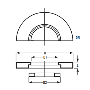
Adaptor bellow flanges are used to fit a bellow to a flange having different bolt configuration. These flanges are made of cast iron and are supplied with a split ring.
These are particularly used to fit a bellow with a non-glass equipment like Glass-lined Reactor etc. These are used in FBF, VBF type PTFE bellows.
Adaptor bellow flanges are generally supplied undrilled. However, if specified, these can be supplied drilled as per \"Table E\", \"Table F\" and \"ASA 150\" standards.
Undrilling flanges
| Cat.Ref. | DN | D | D1 | D2 | L |
|---|---|---|---|---|---|
| BFA0.5 | 12 | 80 | 25 | 28 | 6 |
| BFA0.7 | 15 | 85 | 29 | – | 6 |
| BFA1* | 25 | 115 | 43 | 51 | 7 |
| BFA1.5* | 40 | 150 | 58 | 66 | 7 |
| BFA2* | 50 | 165 | 70 | 81 | 7 |
| BFA3* | 80 | 200 | 101 | 112 | 7 |
| BFA4* | 100 | 220 | 134 | 148 | 8 |
| BFA6* | 150 | 285 | 186 | 196 | 8 |
| BFA9* | 225 | 395 | 260 | 282 | 8 |
| BFA12 | 300 | 445 | 342 | 363 | 10 |
Drilled to Table F
| Cat.Ref. | PCD | n x dØ |
|---|---|---|
| BFA0.5/F | 67 | 4 x 7Ø |
| BFA0.7/F | 67 | 4 x 7Ø |
| BFA1/F | 87 | 4 x 16Ø |
| BFA1.5/F | 105 | 4 x 16Ø |
| BFA2/F | 127 | 4 x 16Ø |
| BFA3/F | 165 | 8 x 16Ø |
| BFA4/F | 190 | 8 x 16Ø |
| BFA6/F | 260 | 12 x 19Ø |
| BFA9/F | 356 | 12 x 23Ø |
| BFA12/F | 438 | 12 x 23Ø |
Drilled to Table E
| Cat.Ref. | PCD | n x dØ |
|---|---|---|
| BFA0.5/E | 62 | 4 x 7Ø |
| BFA0.7/E | 62 | 4 x 7Ø |
| BFA1/E | 82 | 4 x 12Ø |
| BFA1.5/E | 98 | 4 x 12Ø |
| BFA2/E | 114 | 4 x 16Ø |
| BFA3/E | 146 | 4 x 16Ø |
| BFA4/E | 178 | 8 x 16Ø |
| BFA6/E | 235 | 8 x 19Ø |
| BFA9/E | 324 | 12 x 19Ø |
| BFA12/E | 406 | 12 x 23Ø |
Drilled to ASA 150
| Cat.Ref. | PCD | n x dØ |
|---|---|---|
| BFA0.5/A | 62 | 4 x 7Ø |
| BFA0.7/A | 62 | 4 x 7Ø |
| BFA1/A | 79 | 4 x 16Ø |
| BFA1.5/A | 98 | 4 x 16Ø |
| BFA2/A | 121 | 4 x 19Ø |
| BFA3/A | 152 | 4 x 19Ø |
| BFA4/A | 190 | 8 x 19Ø |
| BFA6/A | 241 | 8 x 19Ø |
| BFA9/A | 298 | 8 x 19Ø |
| BFA12/A | 432 | 12 x 23Ø |