 Heat Exchangers
Heat Exchangers
The overall heat transfer coefficient of Borosilicate glass equipment is comparatively favourable with many alternative materials due to its smooth surface, which improves thermal efficiency and reduces fouling. Heat Exchangers are available in 2 basic designs:
- Conventional Coil Type Condensers.
- Shell & Tube Type.
Heat Exchangers
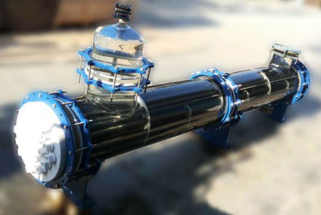
Shell & tube heat exchangers offer large surface area in combination with efficient heat transfer and compactness. These are widely used in industries for various duties like cooling, heating, condensation, evaporation etc. Surya are the pioneers in the field of glass shell and tube heat exchangers in India and their product has a wide market acceptability.
Salient Features of Shell and Tube Heat Exchanger
- Universal corrosion resistance – an excellent alternative to expensive MOCs like graphite, hastelloy, copper titanium, tantalum and other exotic metals.
- Excellent heat transfer as fouling does not occur on smooth glass surfaces.
- Flexibility of installation – vertical/horizontal.
- Easy replacement of tubes for repair and cleaning.
- Available in wide range of HTAs.
- Ease of installation due to light weight.
- Economical.
- Suitable for applications where large HTAs are required in limited space.
Advantages of Shell and Tube Heat Exchanger Over Conventional Coil Type Heat Exchangers
- The overall heat transfer coefficient in shell and tube heat exchanger is about 3 times higher than in coil type heat exchanger.
- The pressure drop in shell and tube heat exchanger is minimal compared to 2–3 kg/cm² in coil side of coil type heat exchanger.
- For requirement of higher heat transfer areas shell and tube heat exchanger is the only alternative.
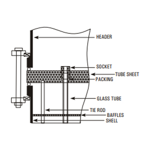
Construction Features of Shell and Tube Heat Exchanger
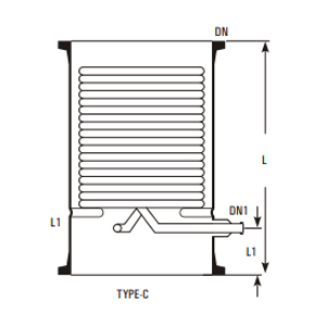
The glass tubes are sealed individually into PTFE tube sheet with special PTFE sockets and packing. This unique ferrule type sealing arrangement permits easy replacement and cleaning of tubes. Baffles on shell side ensure improved heat transfer by increased turbulence. Further details of construction can be seen in the diagram above.
TYPE
Three basic versions * are available:
Material Of Construction of Shell & Tube Heat Exchanger
| Model | Shell | Tube | Header | Duty |
|---|---|---|---|---|
| RGG | Glass | Glass | Glass | For heat transfer between two aggressive media. |
| RGM | Glass | Glass | Steel/FRP | For heat transfer between aggressive media in shell & non-aggressive media in tubes. |
| RMG | Steel/FRP | Glass | Glass | For heat transfer between aggressive media in tubes & non-aggressive media in shell. |
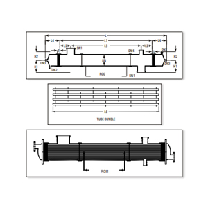
| Specification | 6/3 | 6/4 | 6/5 | 6/6 | 9/6 | 9/8 | 9/10 | 9/12 | 12/12 | 12/16 | 12/21 | 12/25 |
|---|---|---|---|---|---|---|---|---|---|---|---|---|
| Area (m²) | 3 | 4 | 5 | 6 | 6 | 8 | 10 | 12 | 12 | 16 | 21 | 25 |
| DN | 150 | 150 | 150 | 150 | 225 | 225 | 225 | 225 | 300 | 300 | 300 | 300 |
| DN1 | 80 | 80 | 80 | 80 | 100 | 100 | 100 | 100 | 150 | 150 | 150 | 150 |
| DN2 | 50 | 50 | 50 | 50 | 80 | 80 | 80 | 80 | 80 | 80 | 80 | 80 |
| DN3 | 25 | 25 | 25 | 25 | 40 | 40 | 40 | 40 | 40 | 40 | 40 | 40 |
| DN4 | 50 | 50 | 50 | 50 | 50 | 50 | 50 | 50 | 50 | 50 | 50 | 50 |
| H1 | 175 | 175 | 175 | 175 | 250 | 250 | 250 | 250 | 300 | 300 | 300 | 300 |
| H2 | 150 | 150 | 150 | 150 | 200 | 200 | 200 | 200 | 250 | 250 | 250 | 250 |
| L | 2500 | 3100 | 3700 | 4300 | 2620 | 3220 | 3820 | 4520 | 2550 | 3150 | 3950 | 4550 |
| L1 | 1900 | 2500 | 3100 | 3700 | 1900 | 2500 | 3100 | 3800 | 1800 | 2400 | 3200 | 3800 |
| L2 | 150 | 150 | 150 | 150 | 225 | 225 | 225 | 225 | 225 | 225 | 225 | 225 |
| L3 | 1600 | 2200 | 2800 | 3400 | 1450 | 2050 | 2650 | 3350 | 1350 | 1950 | 2750 | 3350 |
| L4 | 250 | 250 | 250 | 250 | 300 | 300 | 300 | 300 | 300 | 300 | 300 | 300 |
| L5 | 125 | 125 | 125 | 125 | 175 | 175 | 175 | 175 | 175 | 175 | 175 | 175 |
| L6 | 1980 | 2580 | 3180 | 3780 | 2000 | 2600 | 3200 | 3900 | 1930 | 2530 | 3330 | 3930 |
| T | 50 | 50 | 50 | 50 | 60 | 60 | 60 | 60 | 75 | 75 | 75 | 75 |
| No. of Tubes | 37 | 37 | 37 | 37 | 73 | 73 | 73 | 73 | 151 | 151 | 151 | 151 |
| No. of Baffles | 11 | 15 | 19 | 23 | 7 | 9 | 13 | 17 | 5 | 7 | 9 | 11 |
Permissible temperature range for both shell & tube sides: −40 °C to 150 °C.
Maximum permissible temperature difference between shell & tube sides: 120 °C.
All sizes & models are suitable for full vacuum on both sides. Maximum limiting pressures are tabulated below.
Maximum Permissible Pressure Range, Kg/cm²(g)
| Model | Side | 150DN | 225DN | 300DN |
|---|---|---|---|---|
| RGG | Shell | 2.0 | 1.0 | 1.0 |
| RGG | Tube | 2.0 | 1.0 | 1.0 |
| RGM | Shell | 2.0 | 1.0 | 1.0 |
| RGM | Tube | 3.5 | 3.5 | 3.5 |
| RMG | Shell | 3.5 | 3.5 | 3.5 |
| RMG | Tube | 2.0 | 1.0 | 1.0 |
The above ranges of applications are admissible limiting values. For each specific case Surya recommends the admissible operating data based on the relations between pressure and temperature, size and model.
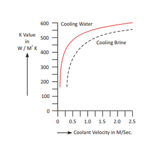
The particular advantage of shell & tube heat exchanger is high heat transfer performance. The relation between heat transfer and velocity of flow can be easily seen in the diagram. On receipt of the operating data from client the most favourable shell and tube heat exchanger is selected. This accurate design combined with most reliable quality assurance ensures economy and operational reliability for the user. For approximate sizing some typical heat transfer coefficients are given here below :
| U-Values | |||
|---|---|---|---|
| Media | Use | kcal/m²hrk | W/m²k300 |
| DN | |||
| Steam water | condensation | 350-550 | 410-640 |
| Water - water | cooling | 250-350 | 290-410 |
| Water - air | cooling | 30-60 | 35-70 |
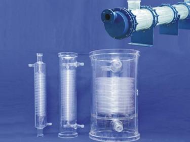
Coil Condensers are used for condensation of vapours and cooling of liquids. Condensers are made by fusing number of parallel coils in a glass shell. Coils are made in different diameters using tubes of different bores.
The average co-efficient of heat transfer in coil condenser is considered as :-
Condensation 200 - 270 Kcal/m², hr, °C appx.
Cooling 100 - 150 Kcal/m², hr, °C appx.
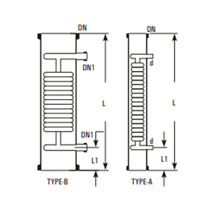
| Cat. Ref. | DN | d/DN1 | L | L1 | Type | Actual H.T.A. m² | Cross Area Cm² | Free Coolant Rate kg/hr. | Max. Jacket Cap. Litre |
|---|---|---|---|---|---|---|---|---|---|
| HE3/3.5* | 80 | 16 | 600 | 75 | A | 0.35 | 5 | 1300 | 2 |
| HE4/5* | 100 | 19 | 600 | 75 | A | 0.50 | 30 | 2400 | 4 |
| HE4/6 | 100 | 19 | 750 | 100 | A | 0.60 | 30 | 2400 | 6 |
| HE6/10 | 150 | 25 | 600 | 100 | B | 1.00 | 52 | 2600 | 9 |
| HE6/15* | 150 | 25 | 850 | 100 | B | 1.50 | 52 | 2600 | 11 |
| HE9/25* | 225 | 25 | 800 | 110 | B | 2.50 | 125 | 3300 | 18 |
| HE12/25 | 300 | 25 | 600 | 125 | B | 2.50 | 175 | 5700 | 25 |
| HE12/40* | 300 | 25 | 900 | 125 | B | 4.00 | 175 | 5700 | 35 |
| HE16/40 | 400 | 25 | 600 | 125 | B | 4.00 | 450 | 6200 | 60 |
| HE16/50 | 400 | 25 | 700 | 125 | B | 5.00 | 450 | 6200 | 70 |
| HE18/60 | 450 | 40 | 750 | 150 | C | 6.00 | 820 | 4800 | 100 |
| HE18/80 | 450 | 40 | 900 | 150 | C | 8.00 | 820 | 6200 | 110 |
| HE24/120 | 600 | 50 | 1250 | 300 | C | 12.00 | 1520 | 6200 | 265 |
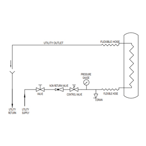
Precautions to be taken in use of coil condensers :
- Vapours should be passed through shell only.
- Maximum pressure of coolant should be 2.7 bars.
- Adequate flow of coolant should be used.
- Steam should not be used in coils.
- Coolant should not be heated to boiling point.
- Coolant control valve should be turned slowly.
- Coolant should be allowed to drain freely.
- Brine can be used in coils in a closed circuit.
- Water main should be connected with flexible hose.
- Ensure no freezing of water remaining in the coils.
- Condensers should be mounted vertically only.
- Condensers can be mounted in series to provide larger surface area.
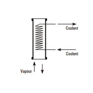
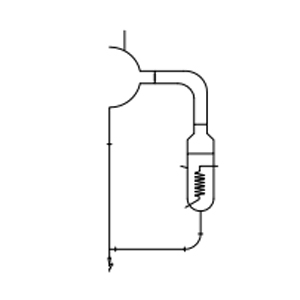
Vapors from bottom
This method is simple to install over a reactor. However this results in condensate returning substantially at its condensing temperature. In this method care must be taken that condensate is not excessive that it can lead to "logging" the coils and create back pressure in the system. Generally a reflux divider is used below the condenser to take out the distillate.
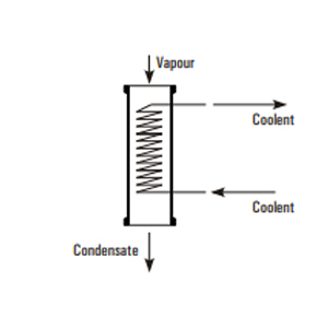
Vapors from top
This method produces a cool condensate using the entire cooling surface area. This method should be used where the condensate can lead to "logging" of coils.
Boilers are used for vaporization of liquids by passing the steam in the coils. Boilers are made by fusing number of parallel coils in a glass shell. In Boilers, coils are designed to provide bigger cross section in the shell side as compared to condensers. The average heat transfer in Boilers is considered as 350 Kcal/m²,hr, °C at a steam pressure of 3.5 bar.
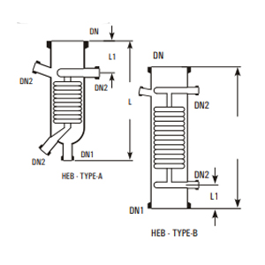
| Cat. Ref. | DN | DN1 | DN2 | L | L1 | Type | Actual H.T.A. m² | Free Cross Area Cm² | Jacket Cap. Litre |
|---|---|---|---|---|---|---|---|---|---|
| HEB4 | 100 | 25 | 25 | 375 | 100 | A | 0.15 | 40 | 2 |
| HEB4/4 | 100 | 100 | 25 | 400 | 100 | B | 0.15 | 40 | 3 |
| HEB6 | 150 | 40 | 25 | 450 | 100 | A | 0.35 | 50 | 5 |
| HEB6/6 | 150 | 150 | 25 | 500 | 100 | B | 0.35 | 50 | 7 |
| HEB9 | 225 | 40 | 25 | 700 | 100 | A | 1.00 | 150 | 16 |
| HEB9/9 | 225 | 255 | 25 | 700 | 100 | B | 1.00 | 180 | 20 |
| HEB12/12 | 300 | 300 | 25 | 700 | 125 | B | 1.30 | 330 | 40 |
Note on use of Boilers
- Steam should be passed in the coils at a maximum pressure of 3.5 bar which is equivalent to a temperature of 147 °C.
- For higher temperature (maximum up to 200 °C) heat transfer fluids can be passed in the coils.
- Cold liquids should be preheated for better results.
- Boilers should be mounted in an external circulatory loop (as shown in figure) and not direct at the bottom of flask or column.
- Under certain circumstances, boilers can be mounted in series to provide larger heat transfer area.
Metal/Plastic angled hose connector assemblies are available to connect the flexible hose to the condensers. These are provided with a mating flange, a rubber gasket and nut bolts.
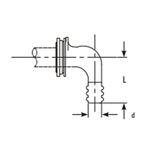
| Cat.Ref. | DN | d | L |
|---|---|---|---|
| PMC1 | 25 | 22 | 70 |
Immersion heat exchangers are used to control exothermic reaction in glass vessels. They can be used with vessels having wider bottom outlet (type VSR and VSE). These are provided with a central hole through the coil battery so that a special, extended type, stirrer can be fitted which extends to the bottom of heat exchanger and provide through action.
In most applications, cooling water is used in coils (max. pressure 2.7 bar g.), but they can also be used with steam (max. pressure 3.5 bar g.). In latter case the coils must be completely immersed in liquid. Immersions are not recommended for use with products which have a tendency to crystalise.
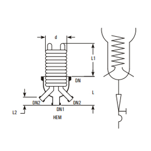
| Cat. Ref. | DN | DN1 | DN2 | L | L1 | L2 | d | Actual H.T.A. m² |
|---|---|---|---|---|---|---|---|---|
| HEM6 | 150 | 40 | 25 | 200 | 200 | 75 | 145 | 0.4 |
| HEM9 | 225 | 40 | 25 | 300 | 200 | 75 | 200 | 0.6 |
Product coolers are used for cooling of liquids, typically, for the cooling of distillates from the distillation columns. Unlike coil condensers, in product coolers, product travels through the coil battery and coolant through shell. This provides more resident time to the product to be cooled. For direct connection with distillate lines, all the product coolers are provided with 25 DN connections.
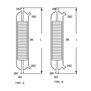
| Cat. Ref. | DN | DN1 | DN2 | L | Actual H.T.A. m² | Type |
|---|---|---|---|---|---|---|
| HEF1/1* | 50 | 25 | 12 | 450 | 0.1 | A |
| HEF1/2* | 50 | 25 | 12 | 600 | 0.2 | A |
| HEF1/3.5* | 80 | 25 | 16 | 600 | 0.35 | A |
| HEF1/5* | 100 | 25 | 19 | 600 | 0.5 | A |
| HEF1/10 | 150 | 25 | 25 | 600 | 0.7 | B |
| HEF1/15 | 150 | 25 | 25 | 850 | 1.25 | B |
When installing coil type heat exchangers appropriate precautions should be taken. The main points to be taken into account when planning to use these items as coolers are (See also flow chart below).