 Pipeline Component
Pipeline Component
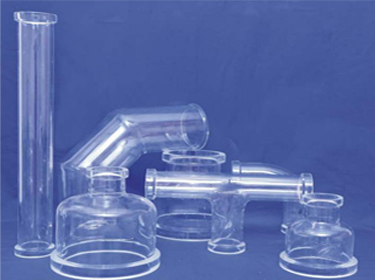
Borosilicate glass 3.3 pipeline offer many advantages for its use in chemical, pharmaceutical industries together.
- Inertness to chemicals – suitable for a wide range of process applications.
- Transparency – allows visual monitoring of the process.
- Universal resistance to corrosion – no contamination of the product.
- Smooth surface – easy to clean and sterilise.
Pipeline Component
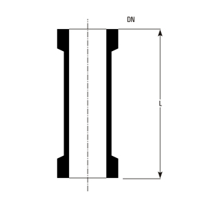 Pipe section (DN = nominal diameter, L = length)
Standard borosilicate glass 3.3 pipe sections for process pipelines. Available in various diameters and lengths to suit your application.
| L | 12 Cat Ref. | 15 Cat Ref. | 25 Cat Ref. | 40 Cat Ref. | 50 Cat Ref. |
|---|---|---|---|---|---|
| 100 | PS0.5/100 | PS0.7/100 | PS1/100* | PS1.5/100* | PS2/100 |
| 150 | PS0.5/150 | PS0.7/150 | PS1/150* | PS1.5/150* | PS2/150* |
| 200 | PS0.5/200 | PS0.7/200 | PS1/200 | PS1.5/200 | PS2/200 |
| 250 | PS0.5/250 | PS0.7/250 | PS1/250 | PS1.5/250 | PS2/250 |
| 300 | PS0.5/300 | PS0.7/300 | PS1/300 | PS1.5/300 | PS2/300 |
| 400 | PS0.5/400 | PS0.7/400 | PS1/400 | PS1.5/400 | PS2/400 |
| 500 | PS0.5/500 | PS0.7/500 | PS1/500 | PS1.5/500 | PS2/500 |
| 600 | PS0.5/600 | PS0.7/600 | PS1/600 | PS1.5/600 | PS2/600 |
| 750 | PS0.5/750 | PS0.7/750 | PS1/750 | PS1.5/750 | PS2/750 |
| 900 | PS0.5/900 | PS0.7/900 | PS1/900 | PS1.5/900 | PS2/900 |
| 1000 | PS0.5/1000 | PS0.7/1000 | PS1/1000* | PS1.5/1000* | PS2/1000* |
| L | 80 Cat Ref. | 100 Cat Ref. | 150 Cat Ref. |
|---|---|---|---|
| 150 | PS3/150* | PS4/150 | PS6/150 |
| 200 | PS3/200 | PS4/200 | PS6/200 |
| 250 | PS3/250* | PS4/250* | PS6/250* |
| 300 | PS3/300 | PS4/300 | PS6/300* |
| 400 | PS3/400 | PS4/400 | PS6/400 |
| 500 | PS3/500 | PS4/500 | PS6/500 |
| 600 | PS3/600* | PS4/600* | PS6/600 |
| 750 | PS3/750 | PS4/750 | PS6/750 |
| 900 | PS3/900 | PS4/900 | PS6/900 |
| 1000 | PS3/1000* | PS4/1000* | PS6/1000* |
| L | 225 Cat Ref. | 300 Cat Ref. | 400 Cat Ref. |
|---|---|---|---|
| 300 | PS9/300 | PS12/300 | PS16/300 |
| 400 | PS9/400 | PS12/400 | – |
| 500 | PS9/500 | PS12/500 | PS16/500 |
| 600 | PS9/600 | PS12/600 | – |
| 750 | PS9/750 | PS12/750 | PS16/750 |
| 900 | PS9/900 | PS12/900 | – |
| 1000 | PS9/1000* | PS12/1000* | PS16/1000 |
| 1200 | PS9/1200 | PS12/1200 | PS16/1200 |
| 1500 | PS9/1500 | PS12/1500 | PS16/1500 |
| L | 450 Cat Ref. | 600 Cat Ref. | 800 Cat Ref. | 1000 Cat Ref. |
|---|---|---|---|---|
| 300 | PS18/300 | – | – | – |
| 500 | PS18/500 | PS24/500 | PS32/500 | PS40/500 |
| 750 | PS18/750 | – | – | – |
| 1000 | PS18/1000 | PS24/1000 | PS32/1000 | PS40/1000 |
| 1200 | PS18/1200 | – | – | – |
| 1500 | PS18/1500* | PS24/1500* | PS32/1500 | – |
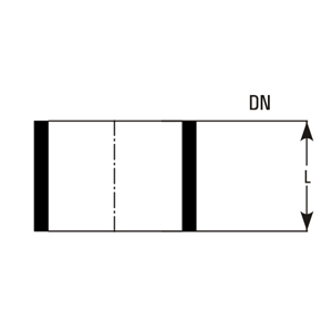 Spacer (DN = nominal diameter, L = length)
Spacers are used to make-up small increments in length.
| L | 12 Cat Ref. | 15 Cat Ref. | 25 Cat Ref. | 40 Cat Ref. | 50 Cat Ref. |
|---|---|---|---|---|---|
| 5 | SS0.5/5 | SS0.7/5 | SS1/5 | SS1.5/5 | SS2/5 |
| 15 | SS0.5/15 | SS0.7/15 | SS1/15 | SS1.5/15 | SS2/15 |
| 25 | SS0.5/25 | SS0.7/25 | SS1/25 | SS1.5/25 | SS2/25 |
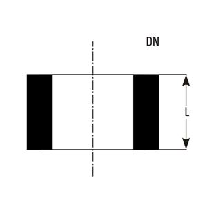 PTFE spacer (DN = nominal diameter, L = length)
PTFE spacers for chemical resistance and thermal stability in pipeline connections.
| L | 12 Cat Ref. | 15 Cat Ref. | 25 Cat Ref. | 40 Cat Ref. | 50 Cat Ref. |
|---|---|---|---|---|---|
| 5 | SST1/5* | SST0.5/5 | SST0.7/5 | SST1.5/5* | SST2/5* |
| 10 | SST1/10* | SST0.5/10 | SST0.7/10 | SST1.5/10* | SST2/10* |
| 15 | SST1/15* | SST0.5/15 | SST0.7/15 | SST1.5/15* | SST2/15* |
| 20 | SST1/20* | SST0.5/20 | SST0.7/20 | SST1.5/20* | SST2/20* |
 Equal tee (DN = nominal diameter, L = length)
Equal tees for branching pipelines with same nominal diameter on all three ports.
| Cat Ref. | DN | L |
|---|---|---|
| PT0.7 | 15 | 50 |
| PT1* | 25 | 100 |
| PT1.5* | 40 | 150 |
| PT2* | 50 | 150 |
| PT3 | 80 | 200 |
| PT4 | 100 | 250 |
| PT6 | 150 | 250 |
| PT9 | 225 | 375 |
| PT12 | 300 | 450 |
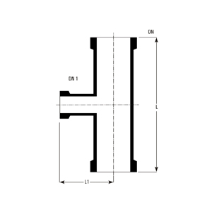 Unequal tee (DN = main run nominal diameter, DN1 = branch nominal diameter, L = length, L1 = branch length)
Unequal tees for branching where branch size differs from the run.
| Cat.Ref. | DN | DN1 | L | L1 |
|---|---|---|---|---|
| PTU1/0.7 | 25 | 15 | 150 | 75 |
| PTU1.5/1 | 40 | 25 | 200 | 75 |
| PTU2/1 | 50 | 25 | 200 | 80 |
| PTU2/1.5 | 50 | 40 | 200 | 100 |
| PTU3/1 | 80 | 25 | 250 | 100 |
| PTU3/1.5 | 80 | 40 | 250 | 100 |
| PTU3/2 | 80 | 50 | 250 | 115 |
| PTU4/1 | 100 | 25 | 250 | 110 |
| PTU4/1.5 | 100 | 40 | 250 | 125 |
| PTU4/2 | 100 | 50 | 250 | 125 |
| PTU4/3 | 100 | 80 | 300 | 150 |
| PTU6/1 | 150 | 25 | 250 | 150 |
| PTU6/1.5 | 150 | 40 | 250 | 150 |
| PTU6/2 | 150 | 50 | 250 | 150 |
| PTU6/3 | 150 | 80 | 300 | 175 |
| PTU6/4 | 150 | 100 | 300 | 200 |
| PTU9/1 | 225 | 25 | 300 | 185 |
| PTU9/1.5 | 225 | 40 | 300 | 185 |
| PTU9/2 | 225 | 50 | 300 | 185 |
| PTU9/3 | 225 | 80 | 300 | 210 |
| PTU9/4 | 225 | 100 | 450 | 250 |
| PTU9/6 | 225 | 150 | 450 | 275 |
| PTU12/1 | 300 | 25 | 400 | 230 |
| PTU12/1.5 | 300 | 40 | 400 | 230 |
| PTU12/2 | 300 | 50 | 400 | 230 |
| PTU12/3 | 300 | 80 | 400 | 275 |
| PTU12/4 | 300 | 100 | 400 | 275 |
| PTU12/6 | 300 | 150 | 450 | 300 |
| PTU12/9 | 300 | 225 | 600 | 300 |
| PTU16/1.5 | 400 | 40 | 400 | 275 |
| PTU16/2 | 400 | 50 | 400 | 275 |
| PTU16/3 | 400 | 80 | 400 | 300 |
| PTU16/4 | 400 | 100 | 400 | 300 |
| PTU16/6 | 400 | 150 | 500 | 350 |
| PTU16/9 | 400 | 225 | 800 | 450 |
| PTU16/12 | 400 | 300 | 800 | 450 |
| PTU18/1.5 | 450 | 40 | 400 | 300 |
| PTU18/2 | 450 | 50 | 400 | 300 |
| PTU18/3 | 450 | 80 | 400 | 320 |
| PTU18/4 | 450 | 100 | 400 | 320 |
| PTU18/6 | 450 | 150 | 600 | 380 |
| PTU18/9 | 450 | 225 | 800 | 400 |
| PTU18/12 | 450 | 300 | 800 | 400 |
| PTU24/4 | 600 | 100 | 600 | 450 |
| PTU24/6 | 600 | 150 | 600 | 450 |
| PTU24/9 | 600 | 225 | 800 | 525 |
| PTU24/12 | 600 | 300 | 800 | 525 |
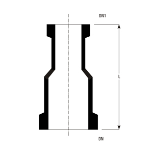 Concentric reducer (DN = large end nominal diameter, DN1 = small end nominal diameter, L = length)
Reducers for connecting pipes of different diameters in the pipeline.
| Cat.Ref. | DN | DN1 | L |
|---|---|---|---|
| PR1/0.7 | 25 | 15 | 100 |
| PR1.5/1* | 40 | 25 | 100 |
| PR2/1* | 50 | 25 | 100 |
| PR2/1.5 | 50 | 40 | 100 |
| PR3/1* | 80 | 25 | 125 |
| PR3/1.5* | 80 | 40 | 125 |
| PR3/2* | 80 | 50 | 125 |
| PR4/1* | 100 | 25 | 150 |
| PR4/1.5* | 100 | 40 | 150 |
| PR4/2* | 100 | 50 | 150 |
| PR4/3* | 100 | 80 | 150 |
| PR6/1* | 150 | 25 | 200 |
| PR6/1.5* | 150 | 40 | 200 |
| PR6/2* | 150 | 50 | 200 |
| PR6/3* | 150 | 80 | 200 |
| PR6/4* | 150 | 100 | 200 |
| PR9/1* | 225 | 25 | 250 |
| PR9/1.5* | 225 | 40 | 250 |
| PR9/2* | 225 | 50 | 250 |
| PR9/3* | 225 | 80 | 250 |
| PR9/4* | 225 | 100 | 250 |
| PR9/6* | 225 | 150 | 250 |
| PR12/1* | 300 | 25 | 300 |
| PR12/1.5* | 300 | 40 | 300 |
| PR12/2* | 300 | 50 | 300 |
| PR12/3* | 300 | 80 | 300 |
| PR12/4* | 300 | 100 | 300 |
| PR12/6* | 300 | 150 | 300 |
| PR12/9* | 300 | 225 | 300 |
| PR16/1.5 | 400 | 40 | 350 |
| PR16/2 | 400 | 50 | 350 |
| PR16/3 | 400 | 80 | 350 |
| PR16/4 | 400 | 100 | 350 |
| PR16/6 | 400 | 150 | 350 |
| PR16/9 | 400 | 225 | 350 |
| PR16/12 | 400 | 300 | 350 |
| PR18/1.5 | 450 | 40 | 375 |
| PR18/2 | 450 | 50 | 375 |
| PR18/3 | 450 | 80 | 375 |
| PR18/4 | 450 | 100 | 375 |
| PR18/6 | 450 | 150 | 375 |
| PR18/9 | 450 | 225 | 375 |
| PR18/12 | 450 | 300 | 375 |
| PR24/4 | 600 | 100 | 400 |
| PR24/6 | 600 | 150 | 400 |
| PR24/9 | 600 | 225 | 425 |
| PR24/12 | 600 | 300 | 425 |
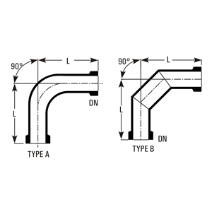 90° bends – Type A (smooth curved elbow), Type B (faceted elbow). DN = nominal diameter, L = length.
90° bends for right-angle direction changes in the pipeline.
| Cat.Ref. | DN | L | TYPE |
|---|---|---|---|
| PB0.7/90 | 15 | 50 | A |
| PB1/90* | 25 | 100 | A |
| PB1.5/90* | 40 | 150 | A |
| PB2/90* | 50 | 150 | A |
| PB3/90* | 80 | 200 | B |
| PB4/90* | 100 | 250 | B |
| PB6/90* | 150 | 250 | B |
| PB9/90* | 225 | 375 | B |
| PB12/90* | 300 | 450 | B |
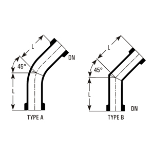 45° bends – Type A (smooth curved), Type B (mitered). DN = nominal diameter, L = length.
45° bends for angled direction changes in the pipeline.
| Cat.Ref. | DN | L | TYPE |
|---|---|---|---|
| PB0.7/45 | 15 | 50 | A |
| PB1/45 | 25 | 75 | A |
| PB1.5/45 | 40 | 100 | A |
| PB2/45 | 50 | 100 | A |
| PB3/45 | 80 | 125 | B |
| PB4/45 | 100 | 175 | B |
| PB6/45 | 150 | 250 | B |
| PB9/45 | 225 | 375 | B |
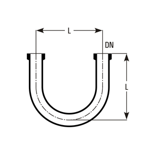 U bend (DN = nominal diameter, L = width / leg length)
U bends for 180° direction change or bypass sections.
| Cat.Ref. | DN | L |
|---|---|---|
| PU0.7 | 15 | 75 |
| PU1* | 25 | 150 |
| PU1.5* | 40 | 175 |
| PU2 | 50 | 175 |
| PU3 | 80 | 225 |
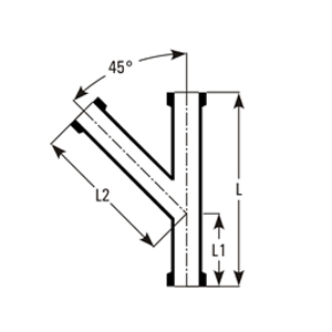 Y bend (DN = nominal diameter, L = main length, L1 = length to branch, L2 = branch length, 45° branch angle)
Y bends for flow splitting or combining in the pipeline.
| Cat.Ref. | DN | L | L1 | L2 |
|---|---|---|---|---|
| PY0.7 | 15 | 125 | 50 | 80 |
| PY1 | 25 | 200 | 75 | 150 |
| PY1.5 | 40 | 250 | 100 | 175 |
| PY2 | 50 | 300 | 125 | 200 |
| PY3 | 80 | 350 | 150 | 250 |
| PY4 | 100 | 450 | 150 | 350 |
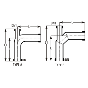 90° bend with thermometer branch – Type A (smooth curved), Type B (mitered). DN = main nominal diameter, DN1 = branch nominal diameter, L = horizontal length, L1 = vertical length to branch end.
90° bends with an integral thermometer branch for temperature monitoring.
| Cat.Ref. | DN | DN1 | L | L1 | TYPE |
|---|---|---|---|---|---|
| PBT1.5 | 40 | 25 | 150 | 225 | A |
| PBT2 | 50 | 25 | 150 | 225 | A |
| PBT3 | 80 | 25 | 200 | 275 | B |
| PBT4 | 100 | 25 | 250 | 325 | B |
| PBT6 | 150 | 25 | 250 | 325 | B |
| PBT9* | 225 | 25 | 375 | 490 | B |
| PBT12* | 300 | 25 | 450 | 560 | B |
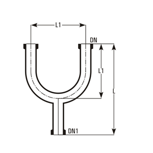 U bend with bottom outlet (DN = main nominal diameter, DN1 = bottom outlet nominal diameter, L = total height, L1 = width / leg length)
U bends with bottom outlet for drainage or sampling.
| Cat.Ref. | DN | DN1 | L | L1 |
|---|---|---|---|---|
| PUO0.7 | 15 | 15 | 150 | 100 |
| PUO1/0.7 | 25 | 15 | 250 | 150 |
| PUO1* | 25 | 20 | 250 | 150 |
| PUO1.5* | 40 | 40 | 275 | 175 |
| PUO1.5/1 | 40 | 25 | 275 | 175 |
| PUO2 | 50 | 50 | 275 | 175 |
| PUO2/1 | 50 | 25 | 275 | 175 |
| PUO3/1 | 80 | 25 | 350 | 225 |
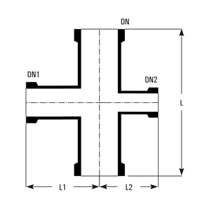 Unequal cross (DN = vertical nominal diameter, DN1/DN2 = horizontal port nominal diameters, L = vertical length, L1/L2 = horizontal arm lengths)
Unequal crosses for multi-directional branching with different port sizes.
| Cat.Ref. | DN | DN1 | DN2 | L | L1 | L2 |
|---|---|---|---|---|---|---|
| PXU2/1/1 | 50 | 25 | 25 | 200 | 80 | 80 |
| PXU2/1.5/1 | 50 | 40 | 25 | 200 | 100 | 80 |
| PXU3/1/1 | 80 | 25 | 25 | 250 | 100 | 100 |
| PXU3/1.5/1 | 80 | 40 | 25 | 250 | 100 | 100 |
| PXU3/2/1 | 80 | 50 | 25 | 250 | 115 | 100 |
| PXU4/1/1 | 100 | 25 | 25 | 250 | 110 | 110 |
| PXU4/1.5/1 | 100 | 40 | 25 | 250 | 125 | 110 |
| PXU4/2/1 | 100 | 50 | 25 | 250 | 125 | 110 |
| PXU4/3/1 | 100 | 80 | 25 | 300 | 150 | 150 |
| PXU6/1.5/1 | 150 | 40 | 25 | 250 | 150 | 150 |
| PXU6/2/1 | 150 | 50 | 25 | 250 | 150 | 150 |
| PXU6/3/2 | 150 | 80 | 50 | 300 | 175 | 150 |
| PXU6/4/2 | 150 | 100 | 80 | 300 | 200 | 150 |
| PXU9/1.5/1.5 | 225 | 40 | 40 | 300 | 185 | 185 |
| PXU9/2/1.5 | 225 | 50 | 40 | 300 | 185 | 185 |
| PXU9/3/1.5 | 225 | 80 | 40 | 300 | 210 | 185 |
| PXU9/4/2 | 225 | 100 | 50 | 450 | 250 | 185 |
| PXU9/6/3 | 225 | 150 | 80 | 450 | 275 | 210 |
| PXU12/2/1.5 | 300 | 50 | 40 | 400 | 230 | 230 |
| PXU12/3/1.5 | 300 | 80 | 40 | 400 | 275 | 230 |
| PXU12/4/1.5 | 300 | 100 | 40 | 400 | 275 | 230 |
| PXU12/6/2 | 300 | 150 | 50 | 450 | 300 | 230 |
| PXU12/9/3 | 300 | 225 | 80 | 600 | 300 | 275 |
| PXU16/1.5/1.5 | 400 | 40 | 40 | 400 | 275 | 275 |
| PXU16/3/1.5 | 400 | 80 | 40 | 400 | 300 | 275 |
| PXU16/4/1.5 | 400 | 100 | 40 | 400 | 300 | 275 |
| PXU16/6/3 | 400 | 150 | 80 | 500 | 350 | 300 |
| PXU16/9/4 | 400 | 225 | 100 | 800 | 450 | 300 |
| PXU18/1.5/1.5 | 450 | 40 | 40 | 400 | 300 | 300 |
| PXU18/3/1.5 | 450 | 80 | 40 | 400 | 320 | 300 |
| PXU18/4/1.5 | 450 | 100 | 40 | 400 | 320 | 300 |
| PXU18/6/3 | 450 | 150 | 80 | 600 | 380 | 320 |
| PXU18/9/4 | 450 | 225 | 100 | 800 | 400 | 320 |
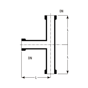
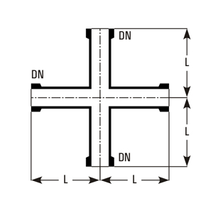 Equal cross (DN = nominal diameter, L = branch length from centre)
Equal crosses for four-way branching with same nominal diameter.
| Cat.Ref. | DN | L |
|---|---|---|
| PX0.7 | 15 | 50 |
| PX1 | 25 | 100 |
| PX1.5 | 40 | 150 |
| PX2 | 50 | 150 |
| PX3 | 80 | 200 |
| PX4 | 100 | 250 |
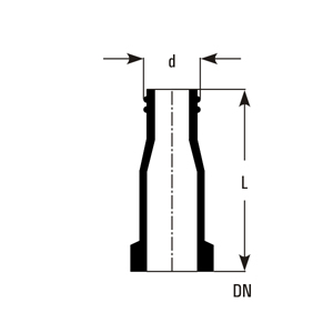
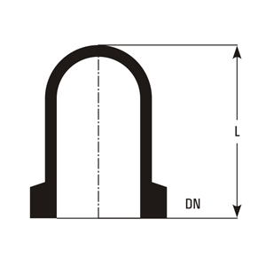 Closure (DN = nominal diameter, L = height/length)
Closures for sealing open pipe ends or unused branches.
| Cat.Ref. | DN | L |
|---|---|---|
| PBE0.7 | 15 | 40 |
| PBE1* | 25 | 50 |
| PBE1.5* | 40 | 75 |
| PBE2* | 50 | 75 |
| PBE3* | 80 | 100 |
| PBE4* | 100 | 125 |
| PBE6 | 150 | 125 |
| PBE9 | 225 | 150 |
| PBE12 | 300 | 150 |
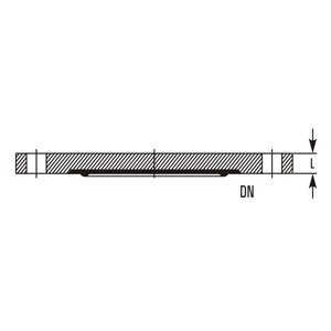 Blind (DN = nominal diameter, L = thickness)
Blinds for positive isolation of pipeline sections when required.
| Cat.Ref. | DN | L |
|---|---|---|
| PBF1* | 25 | 8 |
| PBF1.5* | 40 | 8 |
| PBF2* | 50 | 8 |
| PBF3* | 80 | 8 |
| PBF4* | 100 | 9 |
| PBF6 | 150 | 9 |
| PBF9 | 225 | 9 |
| PBF12 | 300 | 9 |
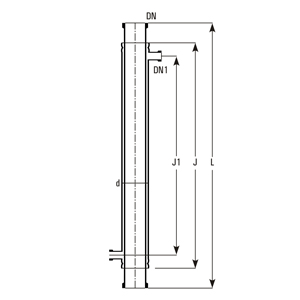 Jacketed pipe section (L = total length, J = jacket length, J1 = internal length, DN = jacket outer diameter, d = inner pipe outer diameter, DN1 = jacket inner diameter)
Glass Jackets
For heating of pipe and for controlling the temperature throughout the column, the jacketed pipe sections are provided. Glass jacket is sealed to the pipe section using Viton 'O' ring and other sealing compositions. The seal prevents impermissibly high stresses between two tubes and allows the movement which comes due to thermal expansion. Maximum operating pressure in the jacket : DN 80 - DN 150 : 1.0 bar; DN 225 - DN 300 : 0.5 bar.
Jacketed pipe sections for heating or cooling of the process stream.
| Cat.Ref. | DN | L | d | DN1 | J | J1 |
|---|---|---|---|---|---|---|
| PSD3/1000 | 80 | 1000 | 100 | 25 | 850 | 750 |
| PSD4/1000 | 100 | 1000 | 150 | 25 | 850 | 750 |
| PSD6/1000 | 150 | 1000 | 225 | 25 | 850 | 700 |
| PSD9/1000 | 225 | 1000 | 300 | 25 | 850 | 700 |
| PSD12/1000 | 300 | 1000 | 400 | 25 | 850 | 650 |
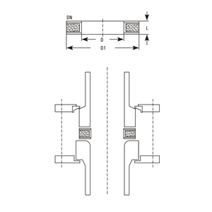 Adaptor plate (DN = nominal diameter of opening, D = inner diameter, D1 = outer diameter, L = thickness)
Adaptor plate for reactors
When reactors have a curved end nozzle, these adaptors are used as interface spacer to connect the glass/bellow with reactor. A flat metal ring with rubber cushions is enveloped with PTFE, to provide ideal sealing. Only PTFE comes in the contact of process fluid.
Adaptor plates for connecting pipeline components to glass reactors.
| Cat.Ref. | DN | D | D1 | L |
|---|---|---|---|---|
| EMP1 | 25 | 25 | 60 | 10 |
| EMP1.5* | 40 | 37 | 80 | 10 |
| EMP2* | 50 | 50 | 100 | 10 |
| EMP3* | 80 | 75 | 120 | 12 |
| EMP4* | 100 | 100 | 155 | 12 |
| EMP6* | 150 | 150 | 210 | 12 |
| EMP9 | 225 | 200 | 260 | 15 |
| EMP12 | 300 | 300 | 360 | 15 |
 Hose connector (DN = nominal diameter, Thread = thread type, d = inner diameter, L = length)
Hose connectors for flexible connection to equipment or hoses.
| Cat.Ref. | DN | Thread | d | L |
|---|---|---|---|---|
| PHC0.5/0.25 | 12 | GL14 | 13.75 | 70 |
| PHC0.7/0.75 | 15 | GL14 | 11 | 70 |
| PHC1/1* | 25 | GL25 | 28 | 90 |
| PHC1/0.75 | 25 | GL18 | 22 | 90 |
| PHC1/0.5 | 25 | GL18 | 15 | 90 |
| PHC1/0.25 | 25 | GL14 | 11 | 90 |
| PHC1.5/1 | 40 | GL25 | 28 | 100 |
| PHC1.5/0.75 | 40 | GL18 | 22 | 100 |
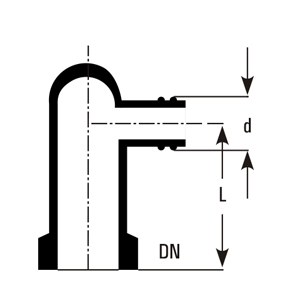 Bend hose connector (DN = nominal diameter, Thread = thread type, d = outer diameter of hose connection, L = height to bend centerline)
Bend hose connectors for angled flexible connections.
| Cat.Ref. | DN | Thread | d | L |
|---|---|---|---|---|
| PBHC0.5/0.25 | 12 | GL14 | 13.75 | 50 |
| PBHC0.7/0.75 | 15 | GL14 | 13.75 | 50 |
| PBHC1/1* | 25 | GL25 | 24.5 | 60 |
| PBHC1/0.75 | 25 | GL18 | 17.5 | 60 |
| PBHC1.5/0.75 | 40 | GL18 | 17.5 | 75 |
| PBHC2/.75 | 50 | GL18 | 17.5 | 100 |